
Design and Implementation of Small Multimedia Active Speaker
Speaker selection The speakers described in this article use anti-magnetic speakers. The tweeter uses the Yindi brand YDQG4-12 tweeter produced by Shanghai Leading Audio Instrument Company. This speaker uses a series of Hi-Fi units such as imported silk diaphragm, magnetic fluid cooling system, fully enclosed anti-magnetic magnetic circuit, etc. The technology makes it have a greater power endurance than the common low-cost tweeters, and the sound quality is more delicate and soft. The subwoofer adopts the South Whale brand 4-inch glue-sprayed paper cone anti-magnetic subwoofer produced by Nanjing Electroacoustic Corporation, model 110-8SX01. The technical specifications of each speaker are shown in Table 1. 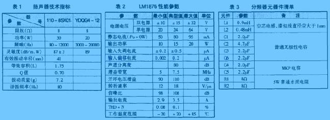
The height, width and depth of this speaker are 280mm × 120mm × 170mm (the internal effective volume is about 3.4L). The board is a medium density board with a thickness of 15 mm. The dimensions of the front panel of the left and right channel speakers are shown in Figure 1. Due to the small size of the speaker, ordinary wood screws can be used to connect the junctions of the panels. 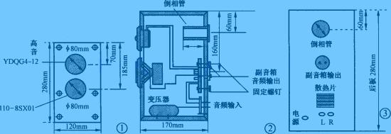
The phase-reversal hole is set above the back of the box, and the length is 68mm. The author cuts a section of 68mm long from a PVC engineering plastic pipe with a diameter of 60mm. Since the inverter tube is on the back of the speaker, the rear panel of the speaker should not be close to the wall when placed, and it should be more than 15cm away from the large surface reflection surface such as the wall. In addition, it should be noted that behind the tweeter unit inside the cabinet, use a sound-absorbing material (sponge) as a shield (enclose the rear of the tweeter unit) to reduce the impact of the sound waves from the bass unit on the tweeter. Interference, making the treble brighter.
The power amplifier circuit is installed in the right channel speaker, so the rear panel layout of the left and right speakers is quite different. The length of the inverter tube and the side view of the main speaker are shown in Figure 2. The rear view of the main speaker is shown in Figure 3.
One of the two speakers is equipped with a power amplifier circuit as the main speaker, and the other as the auxiliary speaker. Because the power transformer needs to be installed in the main speaker and takes up a part of the space, in order to ensure the same internal volume of the two speakers, a wooden block similar to the power transformer volume can be pasted on the bottom of the auxiliary speaker for balance. The decoration on the outside of the cabinet should be freely chosen according to personal preference.
Amplifier circuit The power of this multimedia active speaker is small, and it is enough to use a power amplifier with an output power of about 20W. In order to simplify the circuit, the power amplifier circuit in this speaker uses an integrated circuit, the specific circuit shown in Figure 4. 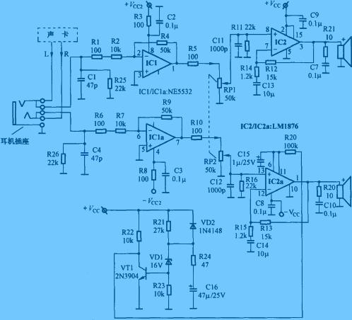
Since ordinary multimedia speakers do not have a headphone output jack, when you need to use headphones, you have to repeatedly plug in and out the plug in the sound card output socket, which brings a lot of inconvenience. For this, I designed a headphone socket in this speaker. When the earphone is not inserted into the socket, the internal contacts of the socket are closed, and the audio signal output by the sound card is directly sent to the power amplifier circuit. When the earphone is inserted, the internal contact of the socket is disconnected, cutting off the wiring from the sound card to the power amplifier. The audio signal output from the sound card is directly sent to the earphone, and there is no sound output from the speaker.
IC1 and surrounding components form a buffer amplifier stage, circuit gain = R4 / (R1 + R2) = 50 / (10 + 0.1) ≈ 5 times. In order to avoid that the input terminal of the preamplifier is left floating and is in a high-impedance input state when the sound card stops working after the computer is turned off, the induced 50Hz AC signal is sent to the post-stage circuit for amplification, so that strong noise appears in the speaker In addition, 22kΩ resistors R25 and R26 are specially set, so that not only can the input impedance be limited to 22kΩ, to prevent the front circuit from working in a high impedance state, but also to effectively suppress the 50Hz induction signal and improve the signal to noise ratio of the whole machine.
The power amplifier integrated circuit adopts the dual-channel 20W high-fidelity power amplifier LM1876 produced by NS Company. The LM1876 is packaged in a 15-pin TO-220, with functions of noise suppression and standby mode. Its main electrical parameters are shown in Table 2.
The load range of LM1876 is very wide, can work stably in the range of 4 ~ 30Ω, the corresponding relation between its output power and load is shown in Figure 5. The power supply voltage range of the LM1876 is ± 10 ~ ± 25V. When the power supply voltage is lowered, it only affects the output power, but has little effect on other indicators. The corresponding relationship between the power supply voltage and output power is shown in Figure 6. Pins 6 and 11 of the LM1876 are the left / right channel squelch control terminal. When these pins are connected to a high level (above 1.6V), the internal circuit of the LM1876 performs a mute operation to cut off the audio signal at the output (as shown in Figure 7) Show). Therefore, an RC delay network can be connected between these pins and the positive voltage to make it high level at the moment of booting, and there is no audio signal output from the output circuit. After a delay, the output is normal, so as to avoid the moment of booting The impact of potential detuning at the output on the speaker. In Figure 4, the transistors VT1, R24, C16, R20, and C15 are the power-on delay network. Adjusting their value range can change the length of the delay time to obtain a satisfactory power-on delay time. 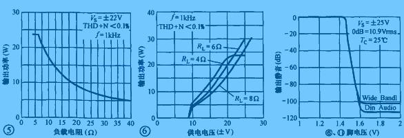
On the one hand, R11 and R16 in the circuit of FIG. 4 are the resistance of the input terminal of the power amplifier circuit in the rear stage, which determines the input impedance of the power amplifier circuit. For example, R11 and R16 are 22kΩ resistors, and the input impedance is 22kΩ. On the other hand, it provides a bias current to the first-stage differential amplifier circuit in the integrated block to make it work normally. It should be noted that the value of R11 and R16 should not be too high, otherwise the midpoint potential of the output terminal will be too high; but it should not be too low, otherwise the input impedance is too low, increasing the power consumption of the previous stage circuit and making the circuit output gain decline. Their value range should be between 15 ~ 51kΩ.
R12 and R14 form a voltage divider, which is connected to the integrated blocks ③ and ⑦ feet to form a negative feedback network. The amplification factor of this circuit is also determined by them, the amplification factor = (R12 + R14) ÷ R14 = (15K + 1.2k) ÷ 1.2k = 13.5. Therefore, as long as the resistance of R12 and R14 is changed, the amplification factor of the circuit can be adjusted, but it should be noted that the amplification factor should be more than 10 times, otherwise the operation of LM1876 will be unstable.
R15 and C7 form a loudspeaker compensation network (also known as a Rubel network), which can absorb the back electromotive force of the loudspeaker and prevent the circuit from oscillating.
C8 and C9 are power supply bypass capacitors (ByPass bypass capacitors), which play the role of reducing the high-frequency internal resistance of the power supply, prevent the circuit from high-frequency self-excitation, and make the LM1876 work more stable.
The resistors in the circuit of Figure 4 are all 1 / 4W five-color ring metal film resistors. The capacitors are all WIMA metallized polypropylene capacitors except C15 and C16. The NE5532 selects the products of the American big S company (Philips products are also available, the unit price is about 10 yuan, and many 2-3 yuan on the market are not recommended). The volume potentiometer is a low-cost and high-quality ALPS product. If you find it difficult to adjust the volume, you can also omit the volume potentiometer and replace it with two 20kΩ resistors in series (pin 8 and pin 13 of the LM1876 are connected to Midpoint of the two resistors). In this way, the volume adjustment of the speaker can be adjusted through the "Volume Control" in the Wndows operating system (double-click or click the small speaker icon in the lower right corner of the monitor to adjust).
The power transformer uses a black and white TV power transformer with an output voltage of 16.5V × 2. The power circuit is shown in Figure 8. 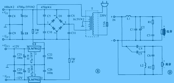
Frequency divider circuit Figure 9 is the circuit diagram of the frequency divider of the speaker, the frequency division point is selected at 3kHz. Because the speaker is an inductive load, when the frequency of the passing signal is different, its impedance changes greatly, so an impedance correction network composed of R1, C3, R2, and C6 is added to the frequency divider to make the load impedance of the frequency divider approximate It is a constant value. The parameters of the components used in the frequency divider are shown in Table 3.
Because the power amplifier block LM1876 will generate a lot of heat during operation, it needs to be installed with a heat sink. The author uses the scraped CPU heat sink to drill two small holes with an electric drill as a heat sink for the power amplifier circuit. When assembling, cut a rectangular hole with the area of ​​the radiator by hand on the back panel of the main speaker, insert the inner wall of the radiator into this hole, seal it with sealant, and then fix the LM1876 to the radiator with bolts Just go (the circuit board must be insulated from the heat sink). The transformer is installed at the bottom of the main speaker (take the right channel as an example), and the power amplifier circuit can be installed in a suitable place in the speaker. The sound-absorbing cotton filled inside the main speaker must not be in contact with the radiator in the power amplifier circuit.
Control impedance PCB
Many customers asked us what information we need for impedence control PCB.Here,there are two types for PCB manufacturer,a is single impedance ,just one trace ,two holes .and b is differential impedance,it always go with 1 pair (two trace with same width and space). For single impedance,you just tell us the trace width one which layer and what value you require .For differential impedance,trace width/space,layers and value. Our experience engineers will calculate following your instruction with Polar software.We may change trace width/space or stackup ,but please do not worry, if any changes,we will send you to approve before proceeding. Generally,the tolerance is 10%,and more accurate is 8% .All impedance boards ,we will test here and report.
Impedance Control Board,Impedance Controlled PCB,Gold Fingers PCB,Impedance Control PCB
Storm Circuit Technology Ltd , https://www.stormpcb.com