
led dot matrix writing display
The design hardware of LED display is mainly composed of the minimum system of STC89C58 single-chip microcomputer, 32 & TImes; 32 two-color dot matrix display array, light pen, buttons, LCD screen and so on. The red LED in the two-color dot matrix always works in a dim scanning state. The STC89C58 microcontroller uses a self-made light pen mid-infrared photoelectric transistor to detect the lighting of the red LED lamp at the position of the light pen, calculate the row and column coordinates of the light pen position, and set according to the buttons. The different working modes of the LED control LED display, so as to realize the functions of lighting, highlighting, reverse display, clearing the screen, dragging the strokes, and taking turns to display. The display screen can automatically adjust the display brightness of the display screen according to the ambient light intensity. When the light pen does not touch the display screen or the buttons are not pressed within the set time, all displays are turned off, and the system is put into a sleep state to reduce power consumption. The system resumes operation when pressed.
Keywords: STC89C58; LED two-color dot matrix; infrared photoelectric tri-plate light pen
0 Introduction In recent years, dot-matrix LED displays have used dot-matrix modules or pixel units composed of light-emitting diodes to form variable-area display screens with high reliability, long service life, strong environmental adaptability, high performance-price ratio, and cost of use. The low-level features have become an electronic tool for many display media and outdoor job displays, and are widely used in advertising such as stations, hotels, finance, securities, post and telecommunications, sports, or transportation and other industries. At present, there are many ways to realize the design of the LED display. This design is based on the STC89C58 microcontroller using a self-made light pen mid-infrared photoelectric transistor to detect the lighting of the red LED lamp at the position of the light pen, calculate the rank coordinates of the light pen position, and The different working modes set by the keys control the LED display, so as to realize the functions of lighting, highlighting, reverse display, clearing the screen, dragging strokes, and taking turns to display.
1 The system design scheme uses a two-color LED dot matrix (red and green) module to form a 32 & TImes; 32 LED dot matrix screen. Among them, the red LED is used for micro-bright scanning detection, the green LED is used for display, and the infrared optical transistor is used to make a light pen. Light up the red LEDs in sequence during detection. When a certain LED is lit, if the light pen is placed on the LED at this time, the resistance of the infrared phototransistor will change, and a high and low can be obtained through the corresponding detection circuit When the level changes, the single-chip microcomputer can judge the current position of the light pen when it detects the signal change.
The scheme is simple and easy to implement, with high sensitivity to the position determination of the light pen, and strong anti-interference ability. The use of two-color dot matrix and infrared phototransistor can effectively reduce the interference of ambient visible light and the light emitted by the display LED (green) on the phototransistor in the light pen.
2 System structure and unit module design
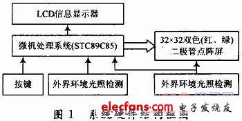
2.1 Overall block diagram of the system The system is mainly composed of microprocessor STC89C58, 32 & TImes; 32 two-color LED dot matrix display, light pen and detection circuit, external light intensity detection circuit, key input circuit, liquid crystal display module and other parts. The block diagram of the system hardware structure is shown in Figure 1.
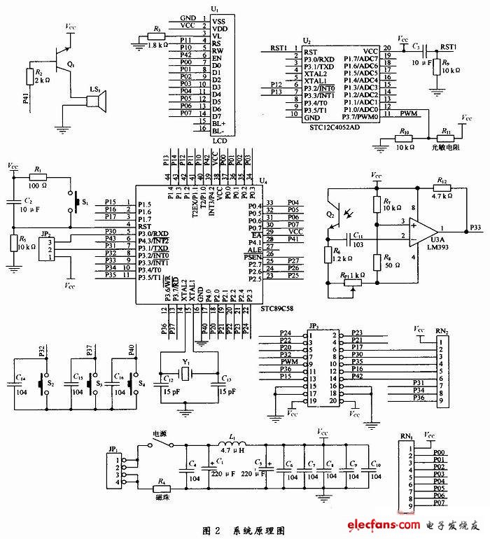
The single-chip microcomputer STC89C58 has 1 KB of off-chip RAM, which can meet the requirements of saving four-screen display information. The single-chip microcomputer has a high cost performance. The system schematic diagram is shown in Figure 2.
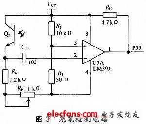
2.2 The light pen and the detection circuit use infrared phototransistors to make the light pen. The light pen detection circuit is shown in Figure 3. In the picture, Q2 is an infrared phototransistor, used to complete the detection of 32 & TImes; 32 dot matrix red LED lights on or off; R6, RP1 is used to limit the current of Q2, in addition, you can also adjust RP1 to increase or decrease the output The voltage value of R7, R8 is used to provide the reference voltage value to the non-inverting terminal of U3A (comparator), through which it is compared with the voltage value output from the collected information (U2> U3, U1 = Umin), R12 is U3A Output pull-up resistor. The working principle is as follows: when the red light shines on the infrared phototransistor, the resistance of the infrared phototransistor becomes smaller, and its emitter voltage rises. At this time, the voltage at pin 2 is higher than the voltage at pin 3, and the output of comparator 1 is low. When the capacitor C11 is charged for a period of time, the voltage at the pin 2 of the comparator is lower than the voltage at the pin 3, and the output of the comparator 1 is high. Thus, when an optical signal is detected, the circuit will generate a pulse signal. Since the coupling capacitor is added in the circuit, the effect of the environment on the light pen can be effectively prevented.
In this system, the light pen is a very important link, in order to better stable work, you must add appropriate anti-interference measures. In terms of signal transmission, shielded soft coaxial copper wire is used, and a black heat shrink tube is added to the periphery of the infrared phototransistor. The infrared phototransistor has a smaller diameter than a single LED lamp to ensure less interference from outside infrared.
2. 3 LED two-color dot matrix display and drive circuit There are many types of LED two-color (red, green) dot matrix, of which the most commonly used are 4 × 4, 8 × 8, 16 × 16 type modules, this design requires a 32 × 32 dual-color display, the display brightness and volume are defined by the designer. Taking into account the factors of purchase, the 32 × 32 dot matrix display screen composed of 16 8 × 8 two-color dot matrix modules is selected. The display is driven by 74HC154 and 74HC595 chips. The serial port works in mode 0 (fast speed). The information is quickly sent to 74HC595.
LED is a non-linear component, when the voltage across it reaches a certain value, the current through it will rise sharply. Consider that the 32 × 32 dot matrix consists of 1,024 light-emitting diodes. When they light at the same time, the current is large, and the power supply capacity must be considered. The current value of the general LED is 5-20 mA, the maximum value is 20 mA, and two lines are lit at the same time, there are: I = 20 × 64 = 1 280mA.
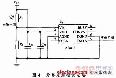
2. 4 external light detection circuit The external light detection circuit is shown in Figure 4. The circuit uses a photoresistor RP in series with a fixed resistor R9 to convert the light change into a voltage change. After the analog-to-digital conversion (A / D) of this voltage signal is passed through the chip AD833, it is sent to the single-chip processor by pin 5 to control the brightness adjustment.
According to the principle of partial pressure, there are: ![]()
It can be seen that choosing a different value of R9 can change the size of Vin, so that the input signal is within a suitable range. The resistance value of the photoresistor RP changes with the light change is 3 ~ 4 kΩ. From the above formula, R9 can be calculated as 3 ~ 4 kΩ, and R9 = 4 kΩ.
2.5 Time-out low-power design Time-out low-power design is implemented by software, using the button to set the time constant, when the light pen does not touch the display or the button is not pressed within the set time, all displays are turned off, and the system enters the sleep state , To reduce power consumption, the system resumes operation when a button is pressed.
A rice cooker or rice steamer is an automated kitchen appliance designed to boil or steam rice. It consists of a heat source, a cooking bowl, and a thermostat. The thermostat measures the temperature of the cooking bowl and controls the heat. Complex rice cookers may have many more sensors and other components, and may be multipurpose. Cooking rice has traditionally required constant attention to ensure the rice was cooked properly, and not burnt. Electric rice cookers automate the process by mechanically or electronically controlling heat and timing, thus freeing up a heating element on the cooking range that had to be otherwise occupied for rice cooking. Although the rice cooker does not necessarily speed up the cooking process, with an electric rice cooker the cook's involvement in cooking rice is reduced to simply measuring the rice, preparing the rice properly and using the correct amount of water. Once the rice cooker is set to cook, the rice will be cooked with no further attention.
Features:
For modern home rice cookers, the smallest single-person model cooks 1 rice cup (180 ml), whereas large models can cook 10 cups. Commercial models can cook 20 or more cups. As a possible source of confusion, model specifications and names may list either cooked or uncooked capacity. Rice roughly doubles in size during cooking; therefore, a 10 cup (uncooked) rice cooker can produce up to 20 cups of cooked rice. The prices vary greatly, depending on the capacity, features, materials used, and the country of origin.
The majority of modern electric rice cookers are equipped with a stay-warm or keep-warm feature, which keeps the rice at an optimal temperature for serving without over-cooking it. Some gas cookers also have electric stay-warm mechanism. However, the usefulness of this feature degrades over time, a microwave may be more energy efficient or better suited to reheat rice that will sit longer than four hours.
Some rice cookers use induction heating, with one or more induction heaters directly warming the pot. This can improve energy efficiency.
Most modern rice cookers use aluminium for the inner cooking bowl. There are some models that use stainless steel instead of aluminium. Various other materials, such as copper, pure carbon, ceramic, and diamond powder coating, may be used for higher heat conductivity or better taste.
The pressure-cooking models can raise the water's boiling point higher, e.g., from 100 °C at 1.0 atm up to about 110 °C at 1.4 atm, which speeds cooking. The pressure-cooking models can also be used in high altitude areas, where the boiling temperature is below 100 Celsius. Pressure cookers are also suitable for cooking brown rice (which contains oils and bran fiber that cook differently from pure white rice starch). Some pressure rice cookers have a varying pressure control mechanism (named the "dual-pressure" method) that creates repeated pressure/release cycles during the cooking.
There also exist mechanisms to collect and return the boiled over liquid to the inner rice bowl.
Many cookers now have microprocessor-controlled cooking cycles, which are often used to adjust for rice and cooking type.
Applications
Rice cookers are typically used for the preparation of plain or lightly seasoned rice. Each rice cooker model may be optimized to cook a certain type of rice best. For example, most Japanese rice cookers are optimized for cooking Japanese rice and may not be the best for other types of rice[citation needed], although cooking time can be lengthened simply by more water.
The typical method of cooking long grain rice is boil-and-strain and/or steaming method. The absorption method used in Japanese rice cookers will produce slightly different texture and taste, usually stickier rice.
Brown rice generally needs longer cooking times than white rice, unless it is broken or flourblasted (which perforates the bran).
Different varieties of rice need different cooking times, depending on their grain size, grain shape, and grain composition. There are three main types of Asian rice: Oryza sativa subsp. indica, i.e., Indian rice (long grain rice, e.g., basmati rice and Thai jasmine rice), O. sativa subsp. javanica, i.e., Java rice (large grain rice) and O. sativa subsp. japonica, i.e., Japanese rice (medium grain rice, e.g., Calrose rice, short grain rice, e.g., most Japanese rice and risotto rice).
African rice, Oryza glaberrima, is an entirely separate species, but can be cooked in the same way. Zizania is not even in the same genus, although it is often called a rice (or "water oats"); it, too, can also be cooked in a rice cooker.
A rice cooker can be used to cook many boiled or steamed granular foods, such as pot barley, bulgar wheat, and dal. Provided the ingredients have similar cooking times, a rice cooker can cook mixtures such as khichdi. Some rice cookers can be used as automated couscoussiers, cooking couscous and a stew simultaneously.
Rice Cooker
Rice Cooker,Drum Rice Cooker,Deluxe Rice Cooker,Straight Rice Cooker
Guangzhou Taipeng Electrical Appliances Technology CO., LTD. , https://www.kettles.pl