
Synchronous Ethernet application solution based on IEEE 1588
1 Background
IP is the development trend of network services in the future, and Ethernet has become the main development direction of IP-based bearer networks due to its superior cost performance, wide application and product support. When deploying carrier-grade Ethernet, how to solve the problem of clock synchronization is an aspect to be considered. There are two aspects to the synchronization requirements of the packet network: First, the packet network can carry the TDM service and provide a mechanism for clock recovery of the TDM service, so that the TDM service still meets certain performance indicators after traversing the packet network; second, the packet network Like a TDM network, a high-precision network reference clock can be provided to meet the synchronization needs of network nodes or terminals.
Synchronous Ethernet (SyncE) is the latest standard solution. In SyncE, Ethernet uses the same method as SONET (Synchronous Optical Network) / SDH (Synchronous Digital Series), and synchronizes its bit clock with a high-quality, traceable first-level reference clock signal. In 2006, the International Telecommunication Union described the SyncE concept in its G.8261. In 2007, the performance requirements of SyncE were standardized in G.8262, and the minimum performance requirements of clocks used in synchronous Ethernet network equipment were specified. IEEE released the IEEE 1588 standard in 2002, which defined a precise time synchronization protocol (PTP). In 2005, a new version of IEEE 1588, ie IEEE 1588v2, was developed.
2 Related standards and agreements
2.1 IEEE 1588
IEEE 1588 achieves more precise timing synchronization through the cooperation of hardware and software. No additional clock line is needed when transmitting time clock signals. The original Ethernet data lines are still used to transmit clock signals, which simplifies networking and reduces costs.
IEEE 1588 specifically defines a set of message-based synchronization protocols in the technical specifications. By periodically publishing time-stamped information packets, the clocks of various measurement and control nodes can be corrected, thereby achieving synchronous operation of the entire system. Its realization principle is shown in Figure 1.
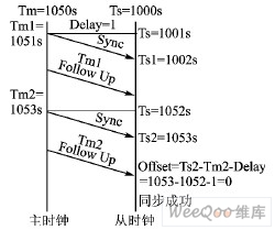
Figure 1 Clock error correction principle
First, the master clock node periodically sends a synchronization packet (Sync) to the entire system (generally 2 s), and then packages the synchronization packet time stamp and then sends a synchronization follow-up packet (Follow Up). When each slave clock node receives the synchronization packet and synchronization follow-up packet from the master clock node, it calculates the master-slave clock difference based on the respective timestamp, received synchronization packet timestamp, and parsing the synchronization follow-up packet timestamp; The value adjusts its own clock until it is synchronized with the main clock.
In the distributed measurement and control system, each measurement and control device's location in the network, wiring method, wiring length, and the inherent problems in the current network technology will also cause different delays in the transmission of measurement and control data. In order to effectively eliminate the impact of network delay on the real-time performance of the distributed system, IEEE 1588 also defines two information packets. The correction principle is shown in Figure 2.

Figure 2 Principle of network delay correction
The slave clock node can send a delay request packet (Delay Request) to the master clock node irregularly (generally 4 to 60 s). After receiving the delay request packet, the master clock node immediately packs the reception time stamp and returns a delay response packet. After receiving the delayed response packet from the clock node, it calculates the network delay time based on the timestamp of the delay request packet sent by itself and the timestamp of the parsed delay response packet, and uses this difference to adjust its own clock until it is synchronized with the master clock. Based on the above method, the master-slave clock difference and the transmission delay of measurement and control data in the network can be effectively eliminated, thereby achieving clock synchronization of the distributed networked measurement and control system.
2.2 Distribution method of reference clock signal
G. 8261 defines the timing synchronization network element in the packet network, stipulates the maximum allowable jitter and drift value in the network, and the minimum value of the jitter and drift tolerance that needs to be achieved when the packet network boundary is connected to the TDM interface; an overview of the network element implementation The minimum requirement of the synchronization function; two distribution methods of the reference clock signal are proposed-network synchronization (synchronous Ethernet) and packet-based, which solves the problem of packet synchronization, especially Ethernet. In particular, the two allocation methods have their own advantages, and their hybrid application will build a next-generation synchronization network that can achieve both frequency synchronization and time synchronization.
(1) Network synchronization method (synchronous Ethernet)
Like the current SONET / SDH link, synchronous Ethernet achieves network synchronization through the first layer (that is, the physical layer) of the OSI seven-layer protocol. Synchronous Ethernet mode is also called "PRC distribution mode" (such as GPS) or the master-slave mode with synchronous physical layer. It supports clock distribution based on the network synchronous line code method and has been widely used in synchronous TMD networks.
Its characteristics are: the use of the Ethernet physical layer; only the synchronization frequency can be allocated, and the synchronization time cannot be allocated; it will not be affected by the damage of the upper layer of the network, and the synchronization quality is good and the reliability is high.
(2) Based on grouping
In this method, the designated time information is carried by the packet, and a special time-stamp message is sent. The method of bidirectionally transmitting timing information may be NTP or a similar protocol. It is worth noting that the two-way protocol can also transmit time information.
Its characteristics are: It has nothing to do with the physical layer; it can allocate synchronization frequency and synchronization time; it will be affected by damage to the telecommunications network, such as packet delay jitter.
3 Application examples
3.1 Si5315 chip
In practical applications, the Si5315 chip produced by Silicon Labs is used. This chip is a jitter-attenuating clock frequency multiplication chip, which uses dual clock input of 8 kHz to * .53 MHz, and generates 2 independent frequency multiplication clocks. In terms of synchronization, Silicon Labs' third-generation DSPLL technology is mainly used, which can generate any ratio of frequency synthesis and debounce at high rates. In addition to supporting SONET / SDH and Ethernet clocks, the Si5315 can also support synchronous Ethernet clock multiplier chips with a 10G line coding rate.
Specific application examples are shown in Figure 3. The local clock input 62.5 MHz is used as one input of the chip, and the output port is 125 MHz after Si5315 frequency multiplication. Introduce its signal into the CDR module (data clock recovery module) of the Ethernet device as a reference clock. When the data enters the CDR, a clock close to 62.5 MHz is recovered, and the Si5315 is input again. After the DPLL phase locks to the clock that the chip thinks meets the requirements, the local clock input is masked. When all the devices on the network complete this operation, the clock synchronization of the entire network is completed. In specific applications, the front-end data clock is often very jittery. After being processed by the Si5315 chip, the clock can be recovered very well, and the clocks of all devices have remained consistent.

Figure 3 Si5315 synchronous chip application example
3.2 DP83640 chip
IEEE 1588's Precision Clock Protocol (PTP) can achieve high-precision Ethernet time synchronization, but if you need to achieve ns-level clock synchronization performance, it is difficult to achieve by software alone. Because after receiving PTP packets on the line, each device that processes them will increase the synchronization error. DP83640 makes ns-level clock synchronization possible by adding hardware and software at the physical layer.
DP83640 is a clock synchronization chip based on the IEEE 1588 standard. It uses hardware and software to provide the highest accuracy of real-time industrial clock synchronization. It can ensure that the distributed nodes can synchronize timing according to the time of the host clock and ensure that each The time deviation between nodes will not exceed 8 ns. Once there is a PTP packet on the line, it is read by DP83640's precision PHYTER.
DP83640 has several internal clocks, including local reference clock, an Ethernet receive clock and a PTP clock signal source; at the same time, it also includes an internal PTP digital counter, and can control the digital counter and PTP clock rate (frequency) Logic.
In the scheme of synchronous Ethernet switch, it is realized by replacing the Ethernet layer and adding IEEE 1588 PTP software. As shown in Figure 4, the CPU, switch chip and DP83640 are connected through the MII port to form a system. The switch becomes a synchronous device in the Ethernet, so that the Ethernet formed by the switch and the devices hung under the network meet the IEEE 1588 protocol, and finally form a synchronous Ethernet.

Figure 4 DP83640-based synchronous Ethernet switch application block diagram
Conclusion
From the perspective of current prototype experiments and applications, the precision time protocol standardized in IEEE 1588 can achieve sub-microsecond synchronization accuracy, and it is possible to achieve higher accuracy. IEEE 1588 provides an effective solution for the real-time application of standard Ethernet based on multicast technology, but there are also some problems that need to be further studied, such as the fault-tolerant performance of the main clock, the impact of the stability of the oscillator on the clock, etc. . I believe that the standard will be more perfect in the future, and there will be more specific applications for reference.
UGR LED Downlight,LED Recessed Downlight,UGR Adjust LED Downlight,UGR LED Commercial Downlight
SHENZHEN KEHEI LIGHTING TECHNOLOGY CO.LTD , https://www.keheiled.com