
Wireless mobile communication based on OFDM
Through some easy-to-understand graphics, the basic principles of Orthogonal Frequency Division Multiplexing (OFDM) and its application in mobile communication are described. Starting from high spectrum utilization and anti-multipath fading, the basic principles of OF DM's advantages are first explained, and then the elimination of ISI and ICI caused by cyclic prefix to time-dispersed channels is analyzed. Finally, the disadvantages of OFDM are explained.
Keywords: OFDM; DFT; multipath fading; ISI; ICI
Wireless Mobile CommunicaTIons Based on OFDM
ZHANG Zhaoxin
(College of Electronic and Informaiton, Hebei University, Baodin g, 071000, China)
Abstract: In this arTIcle, the principle of OFDM and its applicaTIon in Mobile C ommunicaTIons are introduced by several straightaway pictures? Firstly, based on high utilization of frequency spectrum and reduced multi path fading, explains basic cause of bringing about OFDM ′s advantages, secondly, analyzes ISI (Int er Symbol Interference) and ICI (Inter Carrier Interference) cance l lation brought by using Cyclic Prefix in a time dispersive channel? Introduces O FDM ′s disadvantages in the end
Keywords: OFDM; DFT; multipath fading; ISI; ICI
Bandwidth is a scarce resource in mobile communications, so advanced technology must be used to effectively utilize frequency resources, and at the same time, to overcome multipath fading on wireless channels, reduce noise and multipath interference, and orthogonal frequency division multiplexing Multiplex (OFDM) is currently a very promising technology. It is an efficient parallel multi-carrier transmission technology, which decomposes and modulates the transmitted high-speed serial data into multiple parallel orthogonal sub-channels, so that the symbol width of each sub-channel is greater than the channel delay spread, and then passes Cyclic expansion is added to ensure that the system is not affected by inter-symbol interference (ISI) caused by multipath interference. He can effectively combat multipath propagation.
1 Multi-carrier transmission
1.1 Basic principles of multi-carrier
Multi-carrier is to divide the transmission bandwidth into many narrow-band sub-carriers for parallel transmission. Multi-carrier can obtain higher transmission rate in the limited wireless propagation bandwidth. The difference between multi-carrier and single carrier is shown in Figure 1.

For example, to use BPSK modulation signals in a wireless environment to achieve a data rate of 10 Mb / s, a maximum transmission delay of 5 μs, and a bandwidth of 5 MHz. If implemented with a single carrier, the symbol period Tsymb, SC = 0.2 μs, τmax = 25 Tsymb, SC, that is, the inter-symbol interference will continue for 25 symbols. If 128 subcarriers are used for multiple carriers, the duration of each symbol is N (128) times that of a single carrier, τmax = 0.039 NTsymb, SC (NTsymb, SC is the symbol period when multiple carriers), visible between symbols Interference (ISI) has been reduced a lot.
1.2 Orthogonal subcarriers
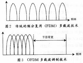
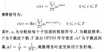
The orthogonality between subcarriers can make the carriers overlap without being distorted by the overlap. Therefore, the use of orthogonal sub-carrier technology can save valuable frequency resources, as shown in Figure 2, Figure 3.
2 Orthogonal Frequency Division Multiplexing (OFDM)
2.1 Basic principles
In an orthogonal frequency division multiplexing system, orthogonal sub-carriers can be obtained by discrete Fourier transform (DFT) (in practical applications, the fast Fourier transform FFT), the baseband signal of OFDM is:
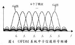
At the receiving end, during the demodulation of the OFDM symbol, the maximum value of each subcarrier frequency corresponding to these points needs to be calculated, because at the maximum value of each subcarrier frequency, the spectrum value of all other subcarriers is exactly 0 (Figure 4 shows the case of 6 subcarriers), so each subchannel symbol can be extracted from multiple overlapping subchannel symbols without interference from other subchannels (assuming accurate synchronization).
2.2 Cyclic expansion
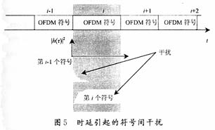
Because each non-zero subcarrier signal is included in each OFDM symbol, and the delay signal of the OFDM symbol also appears at the same time, there will be interference between symbols between wireless channels, as shown in FIG. 5.
Given the system bandwidth and data transmission rate, the symbol rate of the OFDM signal is much lower than that of the single-carrier transmission mode. Because of this low symbol rate, the OFDM system can naturally resist multipath propagation leading to ISI. In addition, through Adding a guard interval at the beginning of each symbol can further resist ISI and also reduce timing offset errors at the receiving end, as shown in Figure 6.
2.3 OFDM system
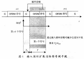
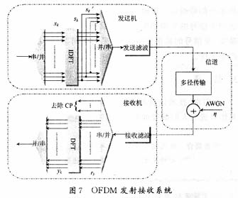
Figure 7 is a traditional OFDM transmission and reception system. The transmitting end converts the transmitted digital signal into a mapping of subcarrier amplitude and phase, and performs inverse discrete Fourier transform (IDFT) to change the spectral expression of the data to the time domain. The receiving end performs the opposite operation to the transmitting end. The amplitude and phase of the subcarriers are collected and converted back to digital signals.
2.4 Disadvantages of OFDM
(1) OFDM is sensitive to system timing and frequency offset
The timing deviation will cause the rotation of the subcarrier phase, as shown in Figure 8, and the phase rotation angle is related to the frequency of the subcarrier. The higher the frequency, the greater the rotation angle. If the timing offset is equal to the length of the maximum delay spread The sum is still less than the length of the cyclic prefix. At this time, the orthogonality between the subcarriers is still established. There is no ISI and ICI (inter-channel interference). The impact on the demodulated data information symbol is only a phase rotation. If the sum of the timing offset and the length of the maximum delay spread is greater than the length of the cyclic prefix, then part of the data information is lost, and the most serious is that the orthogonality between the subcarriers is destroyed, which brings about ISI and ICI, this is one of the key issues affecting system performance.
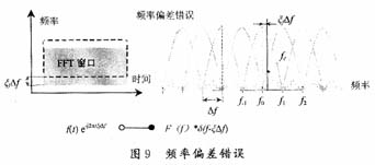
The frequency deviation is caused by the deviation between the local carrier frequencies of the transceiver equipment, the Doppler frequency shift of the channel, etc., and is composed of an integer multiple of the subcarrier spacing and a fractional multiple offset of the subcarrier spacing. The integer multiple of the subcarrier interval will not cause ICI, but the error rate of the demodulated information symbol is 50%. The offset of the submultiple interval of the subcarrier interval is not at the vertex due to the sampling point, as shown in FIG. The orthogonality between them caused ICI.

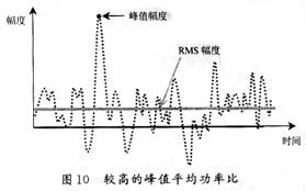
(2) There is a high peak-to-average power ratio
The output of a multi-carrier system is the superposition of multiple sub-channel signals, so if the phases of multiple signals are the same, the instantaneous power of the resulting superimposed signal will be much higher than the average power of the signal, as shown in Figure 10. Therefore, signal distortion may be caused, the frequency spectrum of the signal may change, and the orthogonality between sub-channels may be destroyed, causing interference.
3 Conclusion
OFDM technology has become a research hotspot with its many advantages such as anti-multipath fading and high spectrum utilization, and is expected to become a key technology for the fourth generation of mobile communications. However, there are two fatal shortcomings of OFDM that have become obstacles to the application of OFDM in mobile communications. At present, many scientific researchers are working on this, and OFDM technology is gradually maturing.
references
[1] Tong Xuejian, Luo Tao. Principle and application of OFDM mobile communication technology [M]. Beijing: People ’s University of Posts and Telecommunications Press, 2003
[2] Sensitivity of Orthogonal Frequencydivision Multiple xed Systems to Carrier and Clock Synchronization Errors Signal Processing Steendam, Heidi; Moeneclaey, Marc? 2000,80 (17): 1217-1 229
[3] Wang Wenbo, Zheng Kan. Broadband wireless communication OFDM technology [M]. Beijing: People ’s Posts and Telecommunications Press, 2003
[4] http://tudarmstadt.de/lectures/winter/vlsi_comms/download/chap2_OFDM_ basics.pdf. OFDM Bas ics for Wireless Communications
[5http: //bwrc.eecs.berkeley.edu/People/Grad_Students/dejan/ee225c/ofdm.pdf, OFDM Receiver Design
4G Antenna Description
4G antenna made from alloy material, beautiful appearance, convenient installation, wide frequency range, good performance, has receive a steady, anti salt fog corrosion resistance, anti-jamming, the antenna is arranged at the bottom of the magnet can be adsorbed in the car, easy to use.
4G Antenna Specification
Frequency range: 600-2700MHz
V.S.W.R: ≤1.5
Gain: 3.0-9.0dBi
Polarization: Vertical
Impedance-Ω: 50
Max. Input Power: 50w
Connector: SMA or customized
Cable Length: 3000mm or customized
Radome material: Plastic
Radome color: Black
Operation Temperature: -30~60°C
Humidity: 5~95%
Product show

4G Antenna
4G Antenna,4G LTE Antenna,Indoor Ceiling Antenna,4G LTE Panel Antenna
Shenzhen Yetnorson Technology Co., Ltd. , http://www.yetnorson.com