Making push-pull power amplifier circuit with 6P15 video tube
The construction process for this amplifier is as follows:
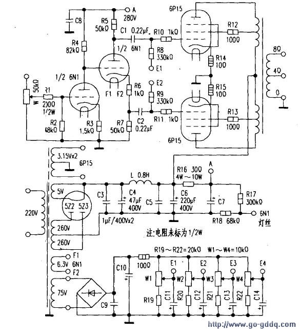
Firstly, considering the fundamental electrical characteristics of the 6P15 vacuum tube, the anode voltage ranges between 300V and 330V, with a current of 30mA, transconductance at 14.7mAN, and output power comparable to both 6P14 and EL84. Using this tube for single-ended amplification results in limited output power, making it impractical for driving speakers with two or more frequency divisions. Thus, a push-pull configuration was designed to achieve an output power of 14W, capable of handling two-way or three-way speakers with sensitivities above 90dB. Such a setup would be ideal for listening environments like living rooms or bedrooms approximately 15 square meters in size. A simplified three-stage amplification is illustrated in Figure 1.
The initial voltage amplification stage employs direct coupling to ensure a broader frequency response. The subsequent stage serves to invert and drive the signal. Additionally, the 6P14, EL84, and 6P15 tubes can be interchanged using certain technical adjustments, ensuring future maintenance and replacement without restrictions.
Secondly, the selection of components for voltage amplification and inversion involves commonly available 6N1, 6N3, and 6N4 series dual triodes (here, 6N1 is utilized). One half of the 6N1 dual triode is employed for voltage amplification, while the other half is used for the drive stage to split the phase of the screen and push the end of the power tube 6P15. The resistances can be set as shown in the diagram (1/2W unspecified), with coupling capacitors C1 and C2 chosen from oil-immersed types of 0.2μF/400V or higher, or alternatively, metalized paper dielectric capacitors. Power supply decoupling capacitors should use oil-filled capacitors or metalized paper capacitors for optimal sound quality.
Thirdly, for push-pull tube gate voltage selection, there are typically two approaches: self-contained gate bias and fixed gate bias. Both methods have their merits; self-biasing eliminates the need for additional transformer windings or grid voltage regulation power supplies but shifts complexity to the next stage, making selection and pairing more challenging. Fixed gate bias voltage requires winding a secondary group of 70V to 100V windings as a gate negative voltage regulating power supply for the push-pull tube's bias voltage. Under identical screen voltages, the self-bias voltage equals the screen voltage minus the gate voltage, whereas the fixed bias voltage resembles the positive and negative power supply of an OCL circuit—screen voltage plus gate negative voltage. Clearly, fixed bias voltage increases the supply voltage and boosts output power. Selecting the tube becomes easier, and balancing the two tubes is straightforward.
Especially for low-power amplifiers, to enhance output power, it is more rational to use fixed gate negative voltage, which explains the choice here.
Fourthly, the power supply requirements and processing appear straightforward, yet it is far from simple, directly affecting the overall performance of the device. Based on the total screen current consumption of four 6P15 tubes, the current of the secondary side high-voltage winding of the power supply is determined, requiring a margin of over 15% to meet the needs of this circuit.
Filament power processing is crucial to eliminate hum. The 6P15 filament power supply is grounded, whereas the 6N1 filament power supply is not directly grounded. Instead, a potential-raising method is used by connecting two resistors via the high-voltage power supply and the ground (R17=300kΩ, R18=68kΩ), dividing the voltage to obtain approximately 70V, which is then connected to the end of the 6N1 filament to eliminate hum. Another often-overlooked aspect is that AC-powered filament power lines are prone to magnetic field radiation, causing hum. In this regard, all AC-powered wires must be twisted and routed. The direction of the twisting should oppose the winding direction of the transformer. This step is essential to minimize hum.
Fifthly, the power transformer and output transformer require a power rating of 120W. The output transformer core cross-sectional area is 22mm x 40mm, with the primary wrapped in φ0.14mm enamel wire for 900+900+900+900 turns, and the secondary wrapped in φ0.83mm enamel wire for 120 turns (4Ω), 160 turns (8Ω). Silicon steel sheets are cross-plugged without leaving an air gap.
Sixthly, the entire machine debugging involves checking the correctness of each solder joint before powering up, ensuring there is no short-circuit in the cross-talk of the connecting lines, and confirming the absence of errors before inserting the tube. Measure the screen voltage at each pin, filament voltage, gate negative voltage, etc. After these checks, adjust the four potentiometers (W1, W2, W3, W4) of the gate negative voltage to the middle position, disconnect the power switch, insert the tube, and connect the output terminal to the speaker to avoid burning the output transformer under no-load conditions. Power on to measure each working point’s voltage, and once it is largely normal, adjust W1 and W2 to ensure the resistor voltage drop (R14 and R15) is 0.25V, with a current of 25mA. For the right channel, adjust W3 and W4, checking every 15 minutes and adjusting once every half hour. Afterward, listening to "Folk Song" by Gong Wangyue revealed soft, sweet tones with every note crystal clear and delightful.
ceramic piston
Yixing Guangming Special Ceramics Co.,Ltd , https://www.yxgmtc.com