Making push-pull power amplifier circuit with 6P15 video tube
The following outlines the construction process:
Firstly, based on the fundamental electrical characteristics of the tube, given that the anode voltage of the 6P15 ranges between 300V to 330V, the current is 30mA, the transconductance is 14.7mAN, and the output power is comparable to both 6P14 and EL84. Using this tube for a single-ended configuration results in limited output power, making it challenging to drive speakers with two or more frequency divisions, which clearly isn't ideal.
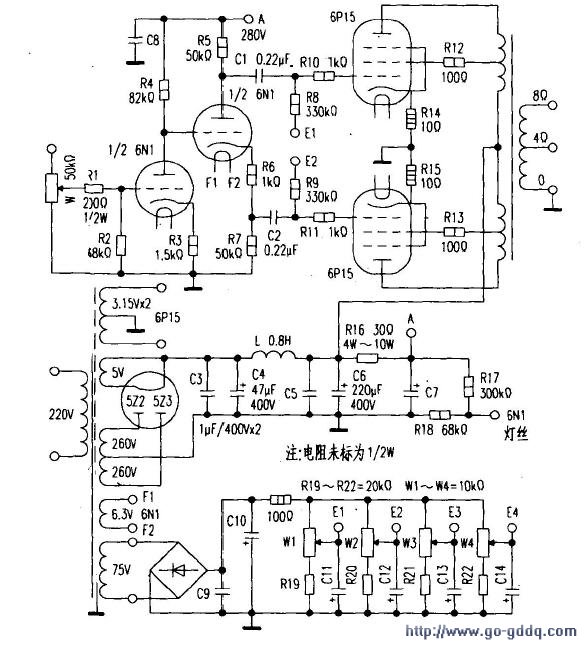
Hence, by designing an ultra-linear push-pull circuit, we achieve an output power of 14W, allowing us to effectively drive two-way or three-way speakers with efficiency above 90dB, suitable for rooms around 15 square meters. A simplified three-stage amplification diagram is provided in Figure 1.
The initial stage of voltage amplification employs direct coupling to ensure a broader channel frequency range, while the subsequent stage performs inversion and driving functions.
Additionally, the 6P14, EL84, and 6P15 can be universally interchanged through specific technical adjustments, ensuring flexibility for future maintenance and exchanges without being restricted by the tube type.
Secondly, for the voltage amplification and inversion sections, common dual-triode series such as 6N1, 6N3, and 6N4 are selected (using 6N1 here). One half of the 6N1 dual-triode is utilized for voltage amplification, while the other half serves the drive stage to split the phase of the screen and push the end power tube 6P15. The resistances can be referenced from the diagram (not specifying the 1/2W). Coupling capacitors C1 and C2 are chosen from oil-immersed types at 0.2μF/400V or higher, or alternatively, metalized paper dielectric capacitors can be used. Power supply decoupling capacitors employ oil-immersed or metalized paper capacitors to enhance sound quality.
Thirdly, for the push-pull tube gate voltage selection, there are typically two methods: self-contained gate bias and fixed gate bias. Each method has its merits. Self-biasing eliminates the need for additional adjustments, eliminating the requirement for winding a transformer or grid negative voltage regulating power supply, though this shifts complexity to the next stage, complicating selection and pairing. Fixed gate bias voltage necessitates a winding of 70V~100V on the transformer's secondary side as a gate negative voltage regulating power supply for the push-pull tube's bias voltage. Under identical screen voltages, self-bias voltage equals the screen voltage minus the gate voltage, whereas fixed bias voltage resembles the positive and negative power supply of an OCL circuit, i.e., screen voltage plus gate negative voltage. Clearly, fixed bias voltage increases the supply voltage and output power, simplifying tube selection and balancing the two tubes effortlessly.
Especially for low-power amplifiers, to boost output power, using fixed gate negative voltage proves more reasonable, which is why this option was chosen.
Fourthly, power supply requirements and processing are seemingly straightforward but are not a simple matter, as they directly impact the entire machine's performance. Based on the total screen current consumption of four 6P15 tubes, the current of the secondary side high-voltage winding of the power supply is determined, requiring a surplus of over 15% to meet the circuit's needs.
Filament power processing is crucial. To eliminate hum, the grounding of the 6P15 filament power supply is grounded. The 6N1 filament power supply is not directly grounded but instead raises the potential by connecting two resistors through the high-voltage power supply and ground (R17=300kΩ, R18=68kΩ), dividing the voltage to generate approximately 70V, which is then connected to the end of F1 of the 6N1 filament to eliminate hum. Another overlooked aspect is that AC-powered filament power lines are prone to magnetic field radiation and produce hum. Thus, all AC-powered wires must be twisted and routed, with the twisting direction opposite to the transformer's winding direction, an essential step to reduce hum.
Fifthly, the power transformer and output transformer require a power transformer of 120W. The output transformer core cross-sectional area is 22mm x 40mm, with the primary wrapped with φ0.14mm enamel wire around 900+900+900+900 turns, and the secondary with φ0.83mm enamel wire wrapped around 120 turns (4Ω), 160 turns (8Ω). Silicon steel sheets are cross-plugged, leaving no air gap.
Sixthly, debugging the entire machine involves checking the correctness of each solder joint before powering on, verifying there are no shorts in the cross-talk of the connecting lines, and ensuring the tube is not inserted until errors are corrected. Measure the screen pressure corresponding to each pin, filament voltage, gate negative voltage, etc., ensuring everything is correct. Then set the four potentiometers (W1, W2, W3, W4) of the gate negative voltage to the middle position, disconnect the power switch, insert the tube, and connect the output terminal to the speaker to avoid burning the output transformer when no load is present. Power on to measure the voltage of each working point, and after basic normalcy, adjust W1 and W2 so that the resistor voltage drops of R14 and R15 are 025V, the current being 25mA; adjust W3 and W4 for the right channel, checking every 15 minutes and adjusting once, half an hour later, listen to "Folk Song" by Gong Wangyue. The sound is soft and sweet, with each note clear and pleasant.
extinguishing cover,electrical systems
Yixing Guangming Special Ceramics Co.,Ltd , https://www.yxgmtc.com