
555-based RS triggering works
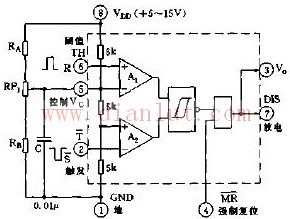
The figure shows the connection diagram using 555 as the RS trigger. If the control voltage of the control terminal 5 is removed, the 555 does not need to be connected to any component. As long as the negative and positive control pulses are added to the 2 and 6 pins respectively, an RS trigger circuit is formed. Here, the R terminal is the reset control input terminal 6 pin, also called the threshold terminal (TH); the S terminal is the set control input terminal 2 pin, that is, the set trigger T terminal. Its output (3 feet) is actually push-pull output inside the chip, its low level output is only about 0.3V, high level is close to VDD, has a very strong load capacity; discharge end (7 feet) is open collector (OC) or open drain (OD) output.
Crystal Clear Back Sticker,Phone Sticker,Mobile Phone Back Skin,Crystal Clear Phone Skin
Shenzhen Jianjiantong Technology Co., Ltd. , https://www.jjtscreenprotector.com