
Application of DNL9308 in the field of digital display automatic control
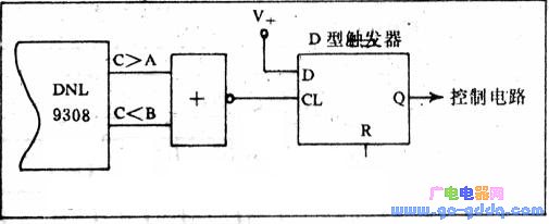
1. Drilling Pressure Control Alarm Device: In geological drilling, the pressure of the drilling tool should be maintained between 1200kg and 1800kg. If the pressure exceeds or falls below this range, it indicates that the tool is operating abnormally or encountering different rock formations. This situation can easily occur when using the DNL9308 depending on the application. To address this, we set comparator A to 1800 and comparator B to 1200. The alarm circuit is formed by using the output signals from the state output port C > A and C ≤ B (see the figure below). Although the pressure sensor and control circuit are not shown here, readers can refer to relevant technical documentation for more details.
2. Thermostat Controller: When high precision is not required, the DNL9308’s C output can be used to control temperature. For example, in a 760°C–780°C heat treatment furnace, we use two state output ports (C > A and C ≤ B) for better control. We set comparator A to 780°C and comparator B to 760°C, and use two electric heaters for heating. When the furnace temperature drops below 760°C, the condition C < B and C < A triggers relay J1 to activate, turning off the auxiliary heater. As the temperature rises to 780°C, the relay J1 deactivates, allowing the heater to restart, thus maintaining the temperature within the desired range.
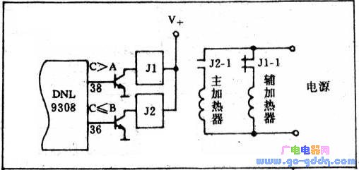
Additionally, the waveform showing the level changes of C ≥ A and C < B helps visualize how the system works. This method ensures stable temperature control and reduces fluctuations.
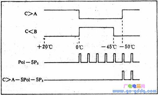
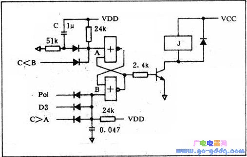
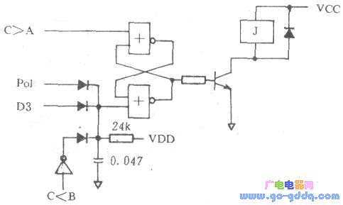
3. Cryogenic Chamber Temperature Control: (1) One common application involves maintaining temperatures between -45°C and -50°C. Here, comparator A is set to -50°C and comparator B to -45°C. As the temperature fluctuates, the system detects when C ≥ A and C < B, triggering the control mechanism. After power-on, a capacitor (1μF) generates a positive pulse at point A, causing relay J to activate until the temperature reaches -50°C. At point B, a reverse pulse resets the bistable circuit, releasing J and allowing the temperature to rise again. Once it hits -45°C, the cycle repeats, keeping the temperature within the desired range.
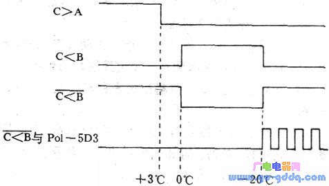
(2) Another low-temperature chamber application requires controlling the temperature between +3°C and -20°C. In this case, comparator A is set to +3°C and comparator B to -20°C. The system uses the conditions C > A and C < B to manage the temperature effectively. This approach allows precise regulation, ensuring stability even under varying environmental conditions.
LCD Interactive Whiteboard,Interactive Intelligent Panel,Smart Interactive Flat Panel,
Shanghai Really Technology Co.,Ltd , https://www.really-led.com