
Characteristic impedance and termination impedance of CAN network
CAN network impedance
The beginning of the problem is started by the CAN network. The following figure is the basic model of a CAN network. The two ends are 120 ohm resistors.
The characteristic impedance of the wire used in the can network is also 120 ohms. Several problems are separately explained below.

1. Why use a 120 ohm termination impedance?
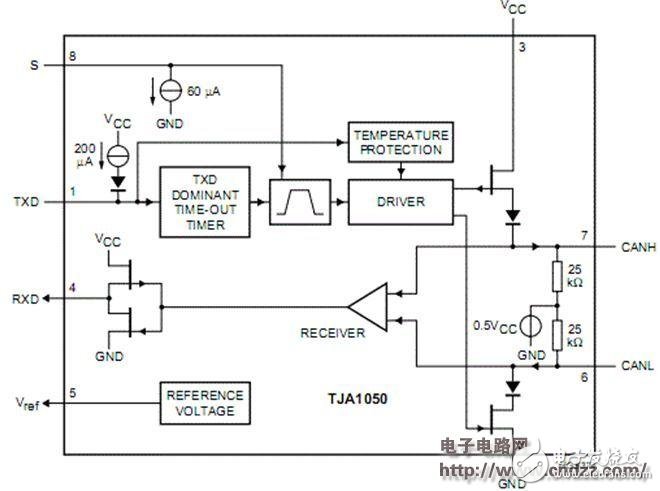
First, the transmission line is used in the CAN network, and the characteristic impedance of the wire is 120 ohms. Regarding the problem below this line, the other thing to explain is the device in the CAN network, that is, the CAN transceiver. The output impedance of this device is very low, and the input impedance is relatively high. See the block diagram of TJA1050. That is to say, the signal transmitted by the characteristic impedance of 120 ohms on the transmission line suddenly reaches a place with high impedance, which can be understood as an open circuit, which will generate high signal reflection, affect the sampling of the level of the CAN transceiver, and cause information errors. read. If a 120 ohm resistor, the terminating resistor, is added between CANH and CANL, because this resistor and the cable have the same characteristic impedance, and the resistor that is much smaller than the output impedance of the CAN transceiver is connected in parallel with the CAN transceiver, the current is naturally more Many of them flow from a small impedance, so that the resistance between them is close to 120 ohms on the cable with a characteristic impedance of 120 ohms, and their signal reflection is much smaller, which can effectively ensure signal integrity. At the same time, this resistor will not affect the signal itself as shown below. For example, in a fault-tolerant CAN network, CANH=3.5v, CANL=0.5v is dominant, CANH=CANL=2.5v is invisible, in dominant position The terminal resistors are 3.5v and 1.5v respectively. One CAN transceiver is the output end. One CAN transceiver is the receiving end, and the output end is at the output voltage. The voltage of CANH and CANL is kept at 3.5v and 1.5v. The voltage difference between them will generate current consumed by the terminating resistor. The CANH and CANL at the receiving end can accurately sample the voltage values ​​of 3.5v and 1.5v. Similarly, when the invisible bit is used, the terminating resistor does not affect the signal of the CAN network. But the effect of impedance matching is achieved.

2. The 120 ohm characteristic impedance wire used in the CAN network, how is the characteristic impedance of the wire defined?
Characteristic impedance is a specific material for a material we are talking about here, because of its thickness, size and other factors. The characteristic impedance of a wire or coaxial cable does not change with the length and the frequency of the transmitted signal (the frequency will be different, but it is very small, theoretically it does not change with frequency), and the characteristic impedance also has its Under the condition of DC, if the impedance of one wire is measured with a multimeter, the result should be Z=0 ohm. However, the characteristic impedance of this and the wire is 50 ohms. The so-called 50 ohm characteristic impedance, its 50 ohm impedance is reflected in the high frequency signal transmission process. It is represented by the following formula, see the following figure:
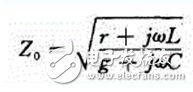
among them
R = the conductor material (in the case of DC) one unit length of resistivity, ohms
G = bypass conductance coefficient per unit length (conductivity of insulating layer), ohm
j=just a symbol indicating that this item has a phase angle of +90' (imaginary number)
Ï€=3.1416
L = inductance of the unit length cable
c=capacity of the unit length cable
Under DC conditions, the R and G in the formula can be neglected. The formula can be simplified to find the square root of L/C. If the wire is short, L should be very close to 0, so the final value is also 0, if this line is very long, then L can not be ignored, and you can see that there is a certain resistance value by measuring with a multimeter.
In the process of high-frequency signal transmission, R and G can not be ignored, and in the rising and falling process of the AC signal, the impedance of the wire is reflected by the inductance and capacitance of the wire.
Feyvan Electronics designs and manufactures NTC temperature sensors, probes, and cable assemblies with excellent long-term stability, high accuracy and short response time in high-temperature sensing applications such as automotive, home appliance and industrial use from -40℃ to +250℃.
With more than 15 years of NTC thermistors and sensor probes production experiences, Feyvan electronics provide various choices for a wide range of applications and are available in custom engineered probe package configurations for a variety of mounting and connectivity options with low costs.
Bullet Sensor
Bullet Sensor,Water Heater Sensor,Radiator Sensor,Sensor Power Supply
Feyvan Electronics Technology Co., Ltd. , http://www.fv-cable-assembly.com