Design of Antenna Crosstalk Simulation System Based on Aircraft
Aeronautical communication systems are becoming increasingly complex, requiring the installation of multiple antennas on a single aircraft. This can lead to crosstalk or co-location interference, which may disrupt the normal operation of the aircraft. In this tutorial, we used COMSOL Multiphysics version 5.1 to simulate interference between two identical antennas mounted on an aircraft fuselage—one for transmission and one for reception—to analyze the impact of crosstalk.
**Streamlined Aircraft**
In the aviation industry, antennas play a critical role in ensuring safe and reliable flight operations. Pilots rely on these antennas to maintain accurate positioning, especially in low visibility conditions such as at night or during bad weather. Therefore, it is essential that these antennas are highly reliable to prevent any potential disruptions.
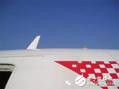
*Close-up view of the aircraft with the antenna mounted on the fuselage.*
Installing multiple antennas on a single aircraft can cause issues like crosstalk or co-location interference. When the electromagnetic signals from one antenna interfere with another, it can significantly affect the performance of the system. For example, when a transmitting antenna sends a signal to the ground, and the receiving antenna is also picking up signals from the same source, interference can occur, potentially disrupting the entire aircraft’s communication.
By simulating antenna crosstalk on the aircraft fuselage, engineers can determine the optimal placement of transmitting and receiving antennas to ensure safe and efficient communication. In this blog, we introduce a new teaching model released with COMSOL Multiphysics 5.1, designed to help visualize and analyze these effects.
**Simulate Crosstalk on the Aircraft Fuselage**
The aircraft model includes a metal fuselage and two antennas—one located on the top and the other on the bottom. The metal surface is modeled as a perfect electrical conductor (PEC), while the surrounding airspace is enclosed by a perfectly matched layer (PML) to simulate an infinite free space environment. This setup ensures that no reflections occur at the boundaries.
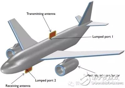
*Schematic highlighting the receiving and transmitting antennas.*
Each antenna consists of a metal strip embedded in a dielectric block. These are designed using a miniaturized bend line configuration, which reduces the input impedance below the standard 50 Ohms. A folded monopole antenna design is used on a large ground plane to match the low impedance.
During the simulation, a lumped port was set up to calculate S-parameters at the gap between the bend line and the fuselage. This helps assess the matching impedance and interference levels between the antennas in different configurations.
The simulation results show the illuminated and shaded areas on the fuselage. The shaded area refers to regions where structures like wings, flaps, or landing gear doors block the energy from the transmitting antenna. The illuminated area, on the other hand, is unobstructed. This means that the receiving antenna should ideally be placed in the shaded area to minimize interference.
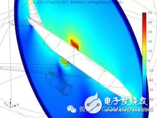
*Electric field strength of the transmitting antenna in three different configurations and its effect on the receiving antenna.*
The simulations were conducted at three different locations along the bottom of the fuselage. The electric field strength and its impact on the receiving antenna were analyzed. It was observed that the shaded area at the tail of the fuselage provided the best performance, confirmed by comparing the S-parameters across the three configurations.
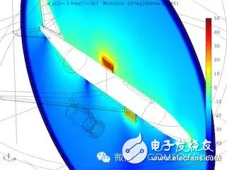
*Shaded areas produced when testing the receiving antennas at three locations.*
By using COMSOL Multiphysics 5.1 and its RF modules, engineers can optimize antenna placement on the fuselage, leading to improved communication performance and safer flights. This simulation not only highlights the importance of proper antenna positioning but also demonstrates how advanced tools can enhance the design process.
20L Agriculture Drone,Agriculture Sprayer Drone,Professional Sprayer Drone,Agriculture Sprayer
Xuzhou Jitian Intelligent Equipment Co. Ltd , https://www.jitianintelligent.com