
Hi-Fi power amplifier circuit and power supply circuit
Hi-Fi power amplifier circuit and power supply circuit
This article refers to the address: http://
As indicated in the chart (from 20W to 80W RMS).
Some explanations:
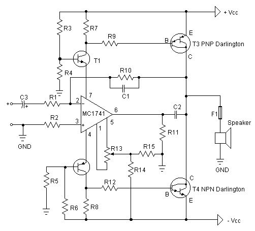
- The first thing you have to do is test the amplification factor hfe or β of the last power tube. If their difference is greater than 30%, the amplifier will not give you a clear sound. I am using MJ3001 and MJ2501 transistors, their The difference is 5%.
- Before turning on the power, you must short-circuit the input, string an ammeter at the output of the amplifier, then turn on the power, adjust R13 to make the ammeter current to microampere level, if you are lucky enough, you can reach 0, the ammeter current is 10 Microamperes are easy to do.
Power amplifier circuit diagram:
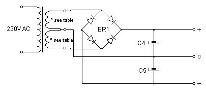
Power circuit:
Component and attribute table:
20 / 35 W | 25 / 40 W | 35 / 60 W | 50 / 80 W | 80 / 125 W | |
T1 | BC546 | ||||
T2 | BC556 | ||||
T3 (PNP Darlington) | BD898, BD678 | BD896, BD676 | BDX34 | MJ900G | 2N6052, MJ2501 |
T4 (NPN Darlington) | BD897, BD677 | BD895, BD675 | BDX33 | MJ1000G | 2N6059, MJ3001 |
C1 | 10 to 12 pF | ||||
C2 | 4.7 to 5.6 nF | ||||
C3 (no polarity capacitor) | 1 to 10 uF | ||||
C4, C5 | 2200 uF / 35 V | 4700 uF / 35 V | 4700 uF / 35 V | 4700 uF / 50 V | 4700 uF / 50 V |
R1, R2, R9, R12 | 10 kΩ | ||||
R3, R4, R5, R6, R14, R15 | 3.3 kΩ | ||||
R7, R8 | 680 Ω | ||||
R10 | 100 kΩ | ||||
R11 | 47 kΩ | ||||
R13 (fine tuning resistor) | 10 kΩ | ||||
F1 (fast) | 1,2 A | 1,6 A | 2 A | 2,2 A | 4 A |
BR1 | B40C1500 | B40C2000 | B40C2800 | B40C3200 | B40C5000 |
Cooler | 4,5 | 2,7 | 2,0 | 1,7 | 1,5 |
Transformer secondary voltage (± 20 %) | 20 + 20 V | 20 + 20 V | 20 + 20 V | 22 + 22 V | 22 + 22 V |
Transformer secondary current | 0,8 A | 1,2 A | 1,3 A | 1,5 A | 2,5 A |
Power (RMS) | 20 W | 25 W | 35 W | 50 W | 80 W |
Music power | 35 W | 40 W | 60 W | 80 W | 125 W |
Minimum speaker impedance | 8 Ω | 8 Ω | 8 Ω | 8 Ω | 4 Ω |
Supply voltage (± 20 %) | ± 25 V | ± 25 V | ± 25 V | ± 30 V | ± 30 V |
Maximum current | 0,54 A | 0,85 A | 1,0 A | 1,15 A | 2,0 A |
Input voltage required for maximum power | 1,8 V | 1,5 V | 1,7 V | 1,95 V | 1,7 V |
input resistance | 10 kΩ | ||||
Bandwidth (-3 dB) | 0 – 100.000 Hz | ||||
THD at 1â„2 P | 0,04 % | ||||
THD at Psin | Max 0,18 % | ||||
Frequency response | 93 dB | ||||
Door Lock Motor Characteristics 1. No direction: don't need to distinguish the door direction, left and right sides, both inside and outside the door, can be universal. (convenient purchase locks and reduce inventory).


2. Power: the power consumption is only equivalent to one 5 of the electric control lock, electric lock, 3 A magnetic lock power to open the door, often consumes 0.27 A. And spiritual lock unlock instantaneous current is less than 0.5 A, reduced the entrance guard, talkback host power consumption.
3. No collision: close the door without collision, reduces the choice of door closers requirements (not necessarily with 65 kg of door closers, door closers are free to choose to suit the door), to solve the building door because the door closers clash of the hydrodynamic force is too high, it is not easy to make the door more deformation, prolong the service life of the body.
4. The voice is light: close the door automatically locked, no noise, solves the noise due to electric control lock itself.
5. Life is long, life is up to 350000 times
Operating temperature range:
Mini Door Lock Motor should be used at a temperature of -10~60℃.
The figures stated in the catalog specifications are based on use at ordinary room temperature catalog specifications re based on use at ordinary room temperature (approximately20~25℃.
If a Lock Motor is used outside the prescribed temperature range,the grease on the gearhead area will become unable to function normally and the motor will become unable to start.Depending on the temperature conditions ,it may be possible to deal with them by changing the grease of the motor's parts.Please feel free to consult with us about this.
Storage temperature range:
lock motor should be stored ta a temperature of -15~65℃.
In case of storage outside this range,the grease on the gearhead area will become unable to function normally and the motor will become unable to start.
Service life:
The longevity of Door Lock Motor is greatly affected by the load conditions , the mode of operation,the environment of use ,etc.Therefore,it is necessary to check the conditions under which the product will actually be used .The following conditions will have a negative effect on longevity.Please consult with us should any of them apply.
â—Use with a load that exceeds the rated torque
â—Frequent starting
â—Momentary reversals of turning direction
â—Impact loads
â—Long-term continuous operation
â—Forced turning using the output shaft
â—Use in which the permitted overhang load or the permitted thrust load is exceeded
â—A pulse drive ,e.g.,a short break,counter electromotive force,PWM control
â—Use of a voltage that is nonstandard as regards the rated voltage
â—Use outside the prescribed temperature or relative-humidity range,or in a special environment.
â—Please consult with us about these or any other conditions of use that may apply,so that we can be sure that you select the most appropriate model.
when it come to volume production,we're a major player as well .each month,we rurn out 600000 units,all of which are compliant with the rohs directive.Have any questions or special needed, please contact us, we have the engineer group and best sales department to service to you
Looking forward to your inquiry. Welcome to our factory.

Door Lock Motor
Door Lock Motor,Mini Door Lock Motor,Door Lock Dc Motor,Door Lock Gear Motor
Shenzhen Shunchang Motor Co., LTD. , http://www.scgearmotor.com