
Single Chip Processor CEPARK USB Development Board Operation Experiment
1, USB false U disk experiment
1) Download the hex file of the USBdisk to the MCU of the USB Development Learning Board
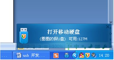
2) At the bottom right of the computer you will see a circle of fake U disk
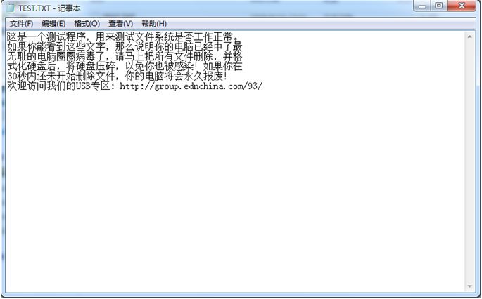
3) Open the U disk of the circle, and you can see a test text file.
2, USB keyboard experiment
Download the hex file of the USB keyboard (USb keyboard) to the MCU of the USB development board
There are 8 buttons on the CEPARK USB development board. The functions are as follows:
Key1: left Ctrl key key2: left Shift key
Key3: left Alt key Key4:0 key
Key5: 1 key Key6: 2 key
Key7: Caps Lock Key8: Num Lock Key
Key function test:
Pressing Key1 and Key2 at the same time can do input method switching, which is the same as the two keys on the keyboard. Key7 can open the capital letter lock, while the second number of lights on the left LED2 lights up. Key8 is a small numeric keypad lock key. When the numeric keypad 2 is turned on, the first light LED1 lights up. At this time, Key4, Key5, and Key6 can be used to input numbers.
Please note that the LEDs on the CEARPK board will be synchronized with the LED lights on your own keyboard. This is true no matter which keyboard switch you press. However, holding down the switch button may cause the LED between the two keyboards to lose synchronization.
After the program is downloaded, you can use the serial debugging assistant to observe the enumeration process. The baud rate is 9600.
3, USB to serial port experiment
Only supports 8 data bits, no parity, no hardware flow control.
The baud rate can support up to 115200bps and 230400bps.
Download UsbToUart's hex file to the SCM of the USb development board
The first time this test is performed, there will be a device in the device manager that does not recognize the devices in the USB to serial port.
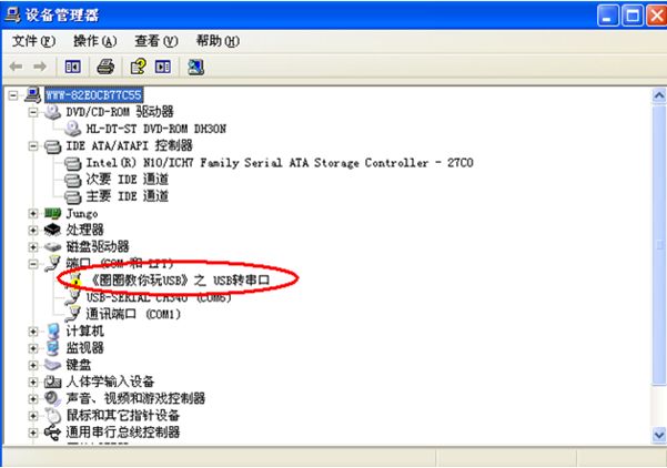
At the same time there will be a wizard to install the hardware;
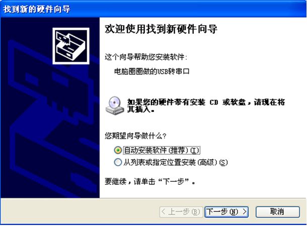
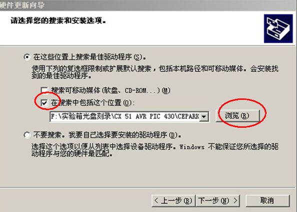
Choose to install from a list or specified location and click Next. The following dialog box will appear;
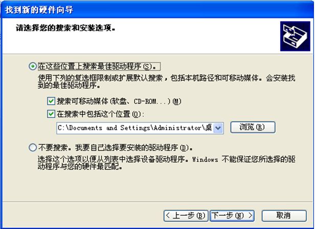
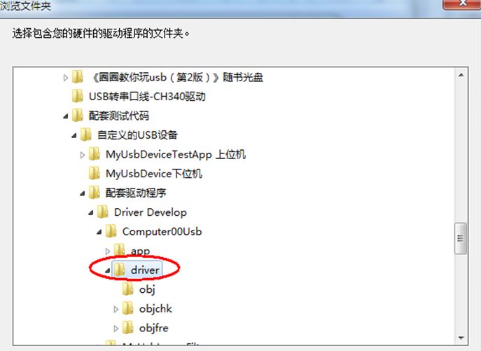
Click Browse and select the driver folder in the folder where this USB-to-serial program is located:
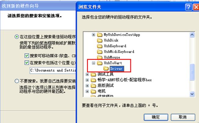
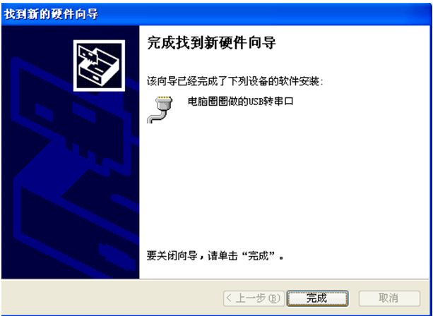
Click OK, Next, there will be a few seconds in the installation process! The installation is complete! Click to finish!

4, custom USB device - My USb device experiment
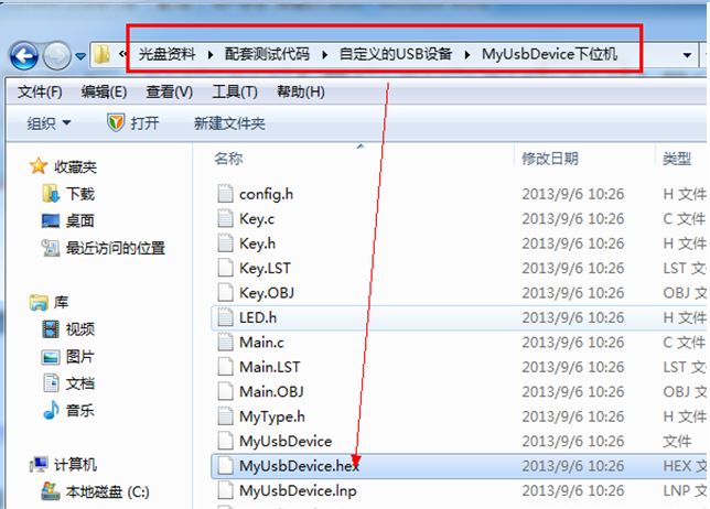
1) First, open the "complementary test code" folder of the CD, find the "custom USB device" folder, find the lower device code of the custom device experiment, as shown below, download the hex file in myusbdevice to usb correctly. Development board
2) After the program is downloaded, the computer automatically finds and installs the corresponding driver. After the driver is properly installed, you will see the device for Computer00usb devices in the Device Manager. Congratulations, your computer has been successfully installed. Circle the driver for the custom USB device.


3) If the above device is not found in Device Manager, please check the following operations
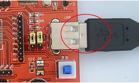
Whether the program is downloaded correctly check the following figure, whether the USB cable is plugged in, and whether the jumper cap is correct
If there is no problem with the hardware and the program, try the following path, find the Computer00usb.sys file
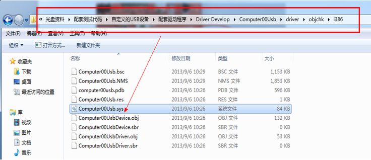
Copy this Computer00usb.sys file to the following path

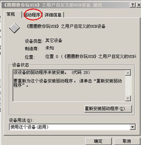
Reopen the board's power switch, open the device manager, and find the unknown device shown below.

Double-click on the device and the device's properties dialog will appear: Click on the driver above
Select Update Driver, a Hardware Update Wizard appears: Select Install from list or specific location, click Next,
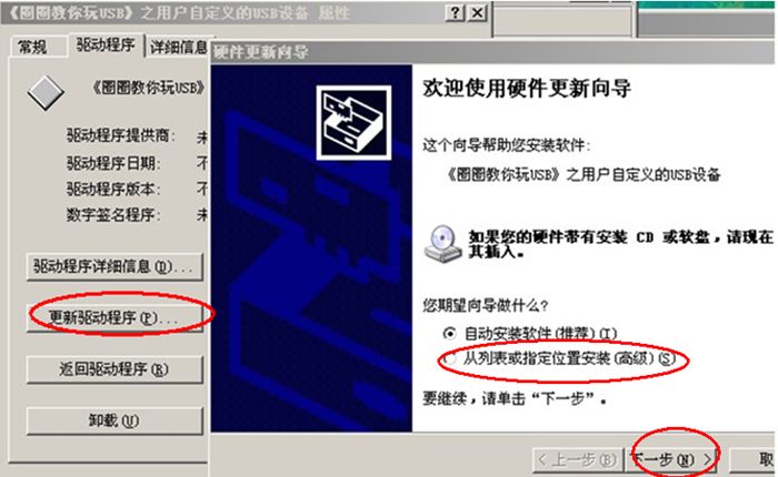
Specify the path to the folder where Computer00usb.sys is stored, as shown below

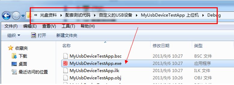
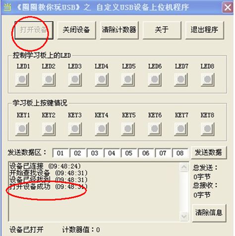
5) Double-click to open, WIN7 system attention, you must open with administrator privileges.
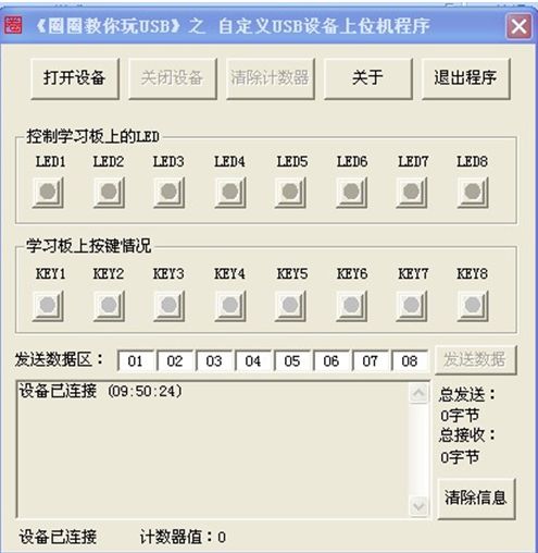
6) Click "Open Device" with the mouse and you will see the prompt "Open Device Successfully" in the lower left corner of the software:
7) Light up the LED of the upper computer, and the corresponding LED on the USB development board will also be lit
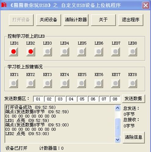
8) Press KEY1 on the USB development board, the corresponding “KEY1†on the upper computer software is lit, release the KEY1 button, the “KEY1†on the software is extinguished, and the rest of the buttons and the small lamp are also the same:

Usually, there are certain restrictions on smart portable projectors in 2 aspects:
1. Size: Usually the size is the size of a mobile phone.
2. Battery life: It is required to have at least 1-2 hours or more of battery life without power connection. In addition, its general weight will not exceed 0.2Kg, and some do not even need fan cooling or ultra-small silent fan cooling. Can be carried with you (it can be put into a pocket, the screen can be projected to 40-50 inches or more, so sometimes we also call it a pico projector or a pocket projector.)
smart portable projector,smart portable projector for iphone,best smart portable projector 2020,cheap smart portable projector,mini smart portable projector wifi
Shenzhen Happybate Trading Co.,LTD , https://www.happybateprojectors.com