
What does the i/o control mean for the microcontroller?
I/O control is one of the most fundamental and essential features of a microcontroller. In fact, apart from analog-to-digital (ADC) and digital-to-analog (DAC) conversion, most other functions can be achieved through I/O operations. While I/O control might seem simple, it offers a wide range of possibilities and variations.
In most applications, the main task of a microcontroller is to read high or low voltage levels and to output high or low voltage levels. This basic level control is what enables most of the functionality in embedded systems.
What is an I/O port?
An I/O port refers to the input or output capability of a microcontroller. It determines whether a specific pin can receive signals (input) or send signals (output).
What are the specific functions of an I/O port?
If you're new to electronics, it's important to understand what an I/O port can do. Having a practical understanding can significantly help in your learning process. For example, an I/O port can output a high or low signal to light up an LED. It can also be connected to a relay to control a motor, activate a buzzer, or even enable communication with other devices. On the input side, it can detect button presses, infrared signals, or other external inputs.
The Relationship Between I/O Ports and Registers
Let’s take a look at the schematic of a microcontroller chip. Pay attention to the RA5 to RA0 pins. 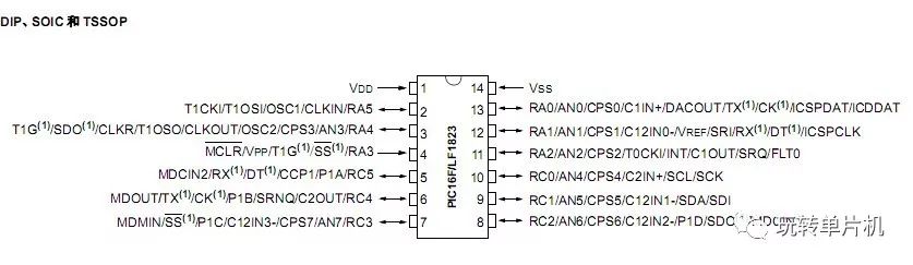
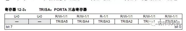
Now, examine the TRISA register, which controls the direction of the RA port.
Next, look at the PORTA register, which controls the data output of the RA port.
  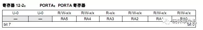
As you can see, the second pin RA5 on the chip corresponds to the TRISA5 bit in the TRISA register and the RA5 bit in the PORTA register. The same applies to RA4 through RA0.
This means that both the TRISA5 bit in the TRISA register and the RA5 bit in the PORTA register are used to control the RA5 pin.
How to Control an I/O Port?
Controlling a microcontroller essentially involves manipulating the bits in its registers. By setting certain bits to high or low, you can control the behavior of the I/O ports. Think of it like having a set of 8 switches, and by pressing or releasing the right ones according to instructions, you can achieve the desired function. Instead of using your hands, we use C language to simulate this process.
The TRISA register is used to set the direction of the I/O port—whether it is an input or an output. For instance, setting TRISAbits.TRISA5 to 0 configures RA5 as an output, while setting it to 1 makes it an input.
Here are a few ways to configure RA5 as an input:
1. TRISAbits.TRISA5 = 1; // Simple and direct, only affects one bit.
2. TRISA |= 0x20; // Less clear, but still affects only one bit.
3. TRISA = 0x20; // Not very clear, but useful when setting multiple I/Os at once.
And here are some ways to set RA5 as an output:
1. TRISAbits.TRISA5 = 0;
2. TRISA &= ~0x20;
3. TRISA = 0x00;
The PORTA register is used to control the actual output value of the I/O pins. If RA5 is configured as an output, then setting PORTAbits.RA5 to 1 will make the pin output a high level, while setting it to 0 will make it output a low level. If RA5 is in input mode, the value of PORTAbits.RA5 reflects the current state of the pin—high or low.
Example Program:
Suppose an LED is connected to the RA5 pin. How would you turn it on?
/*
Development environment: MPLAB X IDE
Chip model: PIC16LF1823
*/
#include <pic.h> // Header file
__CONFIG(FOSC_INTOSC & WDTE_OFF & PWRTE_ON & MCLRE_OFF & CP_ON & CPD_OFF & BOREN_ON & CLKOUTEN_OFF & IESO_ON & FCMEN_ON); // Configuration bits
// Note: This should be placed on the previous line before __CONFIG(PLLEN_OFF & LVP_OFF);
int main(int argc, char** argv) {
ANSELA = 0; // Set all RA pins to digital mode
TRISAbits.TRISA5 = 0; // Set RA5 as output
PORTAbits.RA5 = 1; // Output high level to light the LED
while(1); // Infinite loop
}
Header File: As long as #include <pic.h> is included in the program, the compiler will automatically find the corresponding header file for the chip model. All register addresses and bit definitions are defined in the header file.
Configuration Bits: These are crucial even if the code has no syntax errors. Incorrect configuration can prevent the microcontroller from working properly. You can configure them using the settings in MPLAB X IDE.
Analog/Digital Mode: When using I/O ports, ensure that the corresponding pins are set to digital mode to avoid unexpected behavior.
We offer service for network cabling products in following series: 19" Floorstanding Cabinets in 18U to 45U, Wall mount cabinets and frames, regular patch panel in 6port to 48port,hot sale on 24port cat.5e UTP patch panel,24 port angle patch panels, over 30 kinds of various horizontal and vertical wire management panel,Cat.5e and Cat.6 Patch Cords, toolesskeystone jacks accordingly.

Network cabling products Quality Control Instruction:
To offer a perfect product, we every worker pay attention to each detail of our network cabling products. With our company aim, first in our purchase department, our purchaser compares strictly in raw material suppliers to control cost but keep quality, our mold workshop makes inspection before plastic parts turned to production line .Before installation, our production line first will inspect on plastic parts and other components. During production procedure ,there is tester in steps according different products needs. After installation, the Quality Control members will make a full inspection on characters, appearance according our specification.
19" Floor Cabinet, Cat.5e Patch Panel, Cable Management Bars, Angled Patch Panel, Cat.6a Sheilded Keystone Jack, Cat.6a UTP Keystone Jack, Network Cabling Products, Cat5 Network Cable, Patch Panel.
NINGBO YULIANG TELECOM MUNICATIONS EQUIPMENT CO.,LTD. , https://www.yltelecom.com