
Classic wearable medical circuit collection! Electronic Engineer Design Essentials
Driven by the wave of intelligent hardware, wearable medical equipment has become the blue ocean that all semiconductor manufacturers are chasing. With the shortage of domestic doctor-patient relationship and the shortage of medical resources, the importance of developing wearable medical equipment has become more and more prominent. An excellent wearable medical electronic product must have a unique balance of power consumption, size, performance and other factors, so how to design its internal details? Xiao Bian deliberately compiled six wearable medical electronic circuit diagrams to provide engineers with valuable reference solutions. To learn more about the wearable medical electronic solutions, please pay attention to the topic of electronic enthusiasts' communication of core technologies of the Internet of Things.

Design of sensing circuit for wearable lower limb assisted robot sensing system
Circuit Description : The circuit consists of a detection circuit, a signal amplification circuit and a regulated power supply circuit. The detection circuit is composed of a resistor RH, a transistor VT and resistors R1 and R2; the signal amplifying circuit is composed of A1, RP1, RP2, R3, R4, R6, R5, R8, VD3; the regulated power supply circuit is composed of VD1, VD2, R7, R9, R10, R11, to provide 2.5V regulated power supply for the detection circuit. The resistor RH can be a silicon resistor because the response time of silicon is less than 5S at 25 degrees Celsius. Two TL431s are used in the circuit. The TL431 is a three-terminal adjustable shunt reference source with good thermal stability. Its output voltage can be arbitrarily set to any value from 2.5V to 36V with two resistors. The device's typical dynamic impedance is 0.2Ω, which can be used in many applications to replace Zener diodes, such as digital voltmeters, op amp circuits, adjustable voltage supplies, switching power supplies, and more.
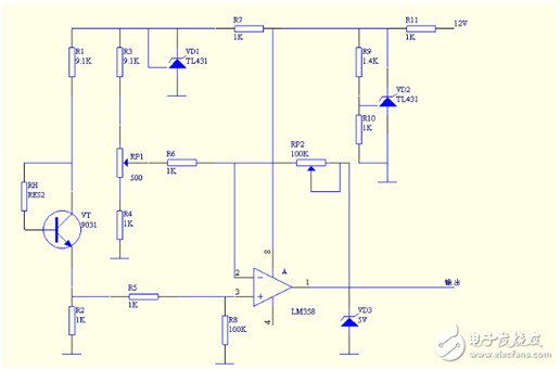
Circuit principle : When the sensor is worn on the body, the RH resistance of the sensor is different due to the different temperature. This resistor becomes the base bias current resistance of VT. The difference in bias current makes the current at the base level different, thus changing the collector current of VT, which changes the VT emitter current. The current of the emitter flows through R2, and the emitter current is converted into voltage on R2. The voltage is sent to the non-inverting input terminal of A1, amplified by A1, and output voltage is controlled by VD3, so that the output voltage is within 5V.
Wearable heart rate signal acquisition preprocessing circuit design
Heart rate signal acquisition preprocessing circuit: The pulse signal acquisition preprocessing circuit mainly converts the pulse wave into an electrical signal and performs preliminary high frequency filtering preprocessing. The key part is the photoelectric pulse sensor. Photoelectric pulse sensors can be divided into transmissive and reflective according to the way of receiving light. Reflective not only can accurately measure the change of blood vessel volume, but in practical applications, the reflection only needs to touch the sensor to any part of the body. When the blood flow of the irradiated part changes with the heartbeat, the infrared receiving probe receives the heart. The arterial pulse pulse signal is periodically contracted and dilated, thereby acquiring a heart beat signal.
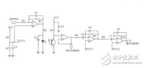
Analysis: This design uses a reflective infrared sensor. The photoelectric pulse sensor uses infrared pair tubes KP-2012F3C and KP-2012P3C, and is reflectively arranged. KP-2012F3C has good skin illumination, the current is generally set at 20mA, and the brightness is controlled by software through PWM current, which can make the infrared LED work in the saturated region and emit light with stable light intensity.
Manually set addresses on the dmx lighting with the Iseeled Address Writer . The Led Address Writer is compatible with most professional lighting. The digital display of Dmx Writer allows for fast and easy setting addresses . ISEELED address writer is convenient for customers setting DMX addresses(such as DMX vertical tube, DMX flood light, DMX pixel lamp and so on)fast and easily. The addresses can be set by individually or uniformly with our address writer. Our address writer has the address setting function itself.
Photo show of Dmx Address Writer:


Dmx Address Writer,Address Writer,Led Address Writer,Dmx Writer
Shenzhen Iseeled Technology Co., Ltd. , https://www.iseeledlight.com