Design and example of high power LED constant current driver
The principle of high-power LED is a process of electro-optical conversion. When a forward bias is applied across the PN junction, the positive charge of the P region will diffuse to the N region due to the decrease of the PN junction barrier, and the electrons in the N region also The P region diffuses while forming an accumulation of non-equilibrium charges in the two regions. Widely used in indoor and outdoor decoration, special lighting, and high-power LED constant current drive scheme is conducive to laying the foundation for new applications.
Constant current driving and improving the optical efficiency of LED are two key issues in LED application design. This paper introduces the application of high-power LED and its selection guide for constant current driving scheme, and then takes National Semiconductor (NS) products as an example. Discuss how to skillfully apply the sampling resistor of the LED constant current driving circuit to improve the efficiency of high power LED, and give attention to the design and heat dissipation design of high power LED driver.
Driver chip selection
LED drivers account for only a small fraction of the cost of LED lighting systems, but they are related to the reliability of the overall system performance. At present, National Semiconductor's LED driver solutions are mainly positioned in the market of high-end LED lighting and lighting. Lighting is divided into indoor and outdoor. Since the power environment used for indoor LED lights has AC/DC and DC/DC converters, the choice of driver chips should also be considered from these two aspects.
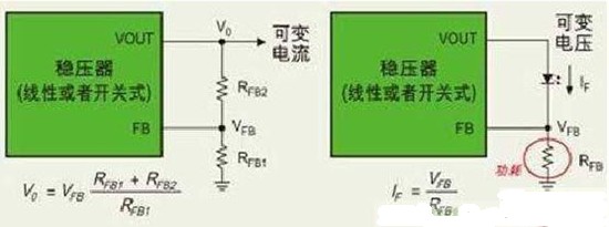
Figure 1: Variable current and variable voltage basic circuits
1, AC / DC converter
The AC/DC is divided into 220V AC input and 12V AC input. 12V AC is the power source for halogen lamps that are widely used in hotels. Existing LEDs can be designed to retain the existing AC 12V. For the design of the replacement halogen lamp, the main advantage of National Semiconductor LM2734 is small size, high reliability, and output current up to 1A, which is suitable for the small diameter of the halogen lamp socket.
After replacing the halogen lamp, the LED lamp is generally made 1W or 3W. The LED lamp has two advantages compared with the halogen lamp: (1) the light source is concentrated, and the brightness obtained by the 1W illumination is equivalent to the brightness of the halogen lamp of ten or more watts, so More power saving; (2) LED lamp life is longer than halogen lamp.
The main weakness of LED lights is that the angle of the light is too narrow and the cost is relatively high. However, in the long run, LED lamps have a very large cost advantage due to their long life. The 220V AC/DC converter (such as the LM5021) is primarily targeted at the stage and streetlight markets.
2, DC / DC converter
At present, LED flashlights account for the vast majority of DC/DC converters. The LED power used in the flashlight is basically 1W, and the power supply method includes a lithium battery, a nickel-zinc battery, and an alkaline battery. The application of 3W flashlight has always had some difficulties, because the 3W LED lamp itself needs heat dissipation, and the heat sink has a large volume, which weakens the advantage of the small size of the LED lamp to a certain extent. In addition, since the current of the 3W LED lamp is as high as 700 mA, the battery life after one charge is shortened. Nevertheless, for the above applications National Semiconductor offers solutions such as LM3475, LM2623A and LM3485.
Miner's lamp is also one of the main application fields of LED lamp. It belongs to the special lighting industry and requires professional certification standards. China has always attached great importance to the application of LED in the field of miner's lamp. At present, the LED design industry has a problem of insufficient understanding of the needs of special industries. Some unrealistic and novel design schemes are often used in the design. For example, the LED lamp and the battery are embedded in the helmet together, but the various needs of the special use environment of the miner's lamp are not taken into account, which may be an important reason for the LED to be used in the miner's lamp market.
For miner's LED applications, National Semiconductor offers a wide range of DC/DC regulator products, including LM3485, LM3478 and LM5010. Users have used a 1W LED lamp and placed 6 ordinary high-brightness LED lights around it. A miner's lamp with special flickering function.
All in all, LED lamps have broad prospects in the lighting and specialty lighting industries, and National Semiconductor offers a complete new LED driver solution.
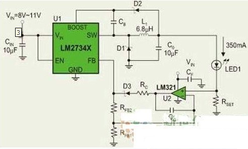
Figure 3: LM2734 based constant current drive circuit
Efficient constant current drive circuit
The basic circuit of the constant voltage power supply (left of Fig. 1) uses feedback resistors RFB1 and RFB2. When the load current changes, VFB also changes. The DC/DC regulator maintains the output voltage at a fixed value by sensing the change of VFB. Level: V0=(VFB*(RFB1+RFB2))/RFB1 (1)
In the circuit on the right side of Figure 1, the FB of the DC/DC regulator is a high-impedance input, and the current IF flowing through the LED is: IF=VFB/RFB (2)
To keep the IF constant, the DC/DC regulator senses VFB and then adjusts the positive voltage of the LED to keep the current through the LED constant. This is the principle of constant voltage to constant current conversion using the FB feedback terminal of the DC/DC regulator.
In general, the DC/DC regulator has a sensing range for VFB changes. Once the LED is selected, the operating current IF is determined. The selected resistor must ensure that VFB falls on the DC/DC regulator. Within the allowable range of the device.
Taking VFB equal to 1.25V as an example, assuming IF is 15mA, 350mA and 700mA respectively, the power consumption of the sampling resistor will be less than 20mW, 400mW and 800mW respectively. For 1W LED, the power consumption of the sampling resistor accounts for the total power consumption. 2%, 40%, and 80%. Therefore, the design of the sampling resistor is critical to improving the efficacy of the LED. It should be chosen to be as small as possible.
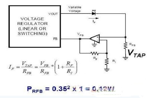
Since directly connecting the RFB to the FB terminal will cause excessive power consumption of the RFB, an operational amplifier is placed between the FB terminal and the RFB to amplify the voltage VTAP collected by the RFB (Fig. 2).
IF=VTAP/RFB=(VFB/RFB)*(1+RF/RI) (3)
Typically, a typical operating current of a 1W high power LED is 350mA. If RFB is chosen to be equal to 1 ohm, the power consumption of the RFB is:
PRFB=I2*R=0.352*1=0.12W (4)
Considering the power consumption of the op amp itself, the power consumption of the RFB and its associated circuits is approximately 12% of the 1W LED power. This reduces the RFB's power consumption to an acceptable level while ensuring constant current supply to the LED. Thus, the voltage across the LED is as large as possible, and the current flowing through is as large as possible. National Semiconductor's regulators operating according to this principle are LM2736 and LM2734.
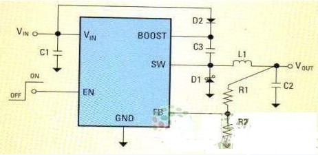
Figure 4 Design of the feedback voltage directly from the sampling resistor
In addition, the optical efficiency of LED lighting systems depends not only on the LED constant current drive scheme, but also on the thermal design of the entire system. In order to reduce the size, some LED constant current drive systems close the LED drive circuit and the heat sink part, which easily affects reliability.
Generally speaking, the heat source of the LED lighting system is basically the heat source of the LED lamp itself, and the heat source is too concentrated to generate heat loss, so the LED driving circuit cannot be closely attached to the heat dissipation system. It is recommended to adopt the following heat-dissipation measures: LED lamp uses aluminum substrate to dissipate heat; power device is evenly arranged; avoiding LED driver circuit and heat-dissipating part close to design as much as possible ; suppressing thermal impedance of package to printed circuit board; improving heat dissipation of LED chip Low thermal impedance.
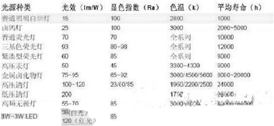
Table 1: High-power LEDs have great advantages in terms of life
New application requirements for the drive
High-power LEDs are called "green light sources" and will evolve toward large LED currents (300mA to 1.4A), high efficiency (60 to 120 lumens per watt), and adjustable brightness.
Due to the great advantages of high-power LEDs in life (Table 1), the development prospects are very broad. The most promising lighting applications are automotive, medical equipment and instrumentation and other special lighting environments. However, these applications also put forward new requirements for LED drive system design, including: input voltage range is generally required to be 6V to 24V; with shock load protection, reverse phase and overvoltage protection; standby power consumption is very low; low bandgap reference Reduce current detection loss and function with PWM brightness adjustment.
In response to these needs, National Semiconductor offers a full range of LED driver designs (see Table 2) that provide users with a comprehensive LED driver solution.
LED lighting systems need to be powered by constant current. The current mainstream constant current driving design uses a linear or switching DC/DC regulator combined with a specific feedback circuit to provide constant current supply to the LED, according to the periphery of the DC/DC regulator. The difference in circuit design can be divided into inductive LED driver and switching power
Capacitive LED driver. The inductive boost driver solution has the advantages of high drive current, low terminal voltage of the LED, low power consumption, and constant efficiency, especially suitable for driving multiple LED applications. In the design of high-power LED driver, the switch-capacitor LED driving scheme is mainly used, and the advantage is that the voltage at both ends of the LED is high and the current flowing is large, thereby obtaining high efficiency and optical efficiency. Advanced switched-capacitor technology also increases efficiency and is therefore widely used in high-power LED drivers.
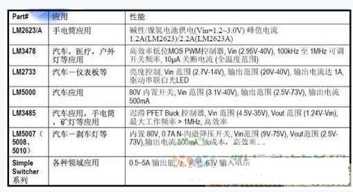
Table 2: National Semiconductor's LED Driver Solutions List
At present, LED lighting has received wide attention from the society. The high-power LED light-efficiency improvement space is still very large, and the high-power LED constant current driving scheme can play an important role in the development of new applications. It is believed that LED lighting will be applied in the near future. every industry.
For information about LED drivers and high-power LED manufacturers, please click: http:// , http://
Gun safe
Gun safes are secure and protective storage containers for one or more firearms, and/or ammunition for the respective firearms.
Details:
Safes are entirely made of steel;
Made by superior fire-proof materials and special sealing materials;
Shelves are removable and adjustable;
Door bolts are in a 4 way coverage;
All gun safes passed CE certification.
Gun Safety,Fire Proof Gun Safe,Furniture Fireproof Safe ,Fireproof Rifle Safe
YONGFA INTELLIGENT TECHNOLOGY SECURITY CO., LTD. , http://www.yongfa-safe.com