
Must know: optical performance of COB packaged LED
In recent years, the COB (chip on board) series of applications in the LED device series has grown rapidly. LED COB (chip on board) package refers to the LED chip is directly fixed on the printed circuit board (PCB), for engagement LED packaging technology of the electrical connection by wire bonding between the chip and the circuit board. It can package tens or even hundreds of chips in a small area, and finally form a surface light source.
Compared with the point source package, the COB surface light source package technology has the advantages of low price (only about 1/3 of the same chip), space saving, easy heat dissipation, improved luminous efficiency, and mature packaging technology. Due to high luminous efficiency and low manufacturing cost, COB packaged LED light sources are popular among many packaging companies.
For a product, the most important thing is its color temperature, luminous flux and light efficiency. For high-power COB packages, the package structure, current size, and thermal performance all affect the optical performance of the LED.
Some people have studied COB different packaging processes and materials, but did not conduct in-depth research on current and lighting time. In this paper, 3 and 10 strings of COB packages were studied to test the data under different currents and lighting at different times, and the factors affecting optical performance were analyzed by data analysis.
1, experiment
1.1 Product preparation
The sample after passing the LED through crystal expansion, spot silver paste, solid crystal, drying, and binding is shown in Fig. 1. Then apply an appropriate amount of phosphor through the color temperature requirement. The test was tested by the software ZWL3907 to determine its color temperature, and then baked and cured, as shown in Figure 2.
1.2 Test methods
The middle is a powder filling machine (0.5m large integrating sphere) as shown in Figure 3. Light color tests were performed on samples with different currents and lighting for different times. Different currents are tested by setting the software test to 500mA, 600mA, 700mA, 800mA, and 900mA respectively. The lighting is used to illuminate for 1min, 5min, and 10min respectively with constant current source, and a Heat Sink is needed when lighting. (Figure 4) to dissipate heat, otherwise it will burn out.
2, analysis and discussion
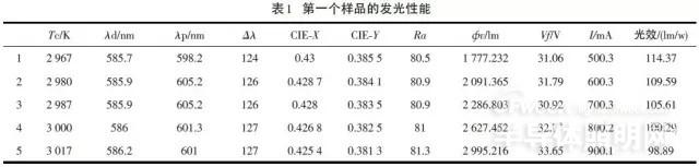
Two samples with a color temperature of about 3000K were placed in a large integrating sphere, and the currents were set to 500 mA, 600 mA, 700 mA, 800 mA, and 900 mA, respectively, and the color temperature, luminous flux, and luminous efficacy were tested. The results are shown in Table 1.
Skiving through mechanical action, the long strip plate cuts the material out of sheets and straightens at a certain angle, and repeatedly cuts to form a uniform clearance structure. It is used to solve the heat dissipation of high power devices under the condition of air cooling and heat dissipation, which can improve the heat dissipation efficiency by 8 ≤ 15% compared with the insert heatsink.
Skived Fin,Skiving Process,Skiving Fin Heatsink,Gear Skiving Process
Dongguan Formal Precision Metal Parts Co,. Ltd , https://www.formalmetal.com