
Design and Implementation of Auto Lamp Control System Based on XC164CM
The car light control system developed in this paper adopts LED lights with high luminous brightness, fast response speed, harsh environment resistance and reliable working performance, which improves the light brightness and viewing angle range, reduces the safety distance, and effectively improves the driving safety performance. The system uses sensor technology, microprocessor technology, electronic circuit technology and CAN bus technology to accurately sense and judge the environmental brightness and driving conditions, and automatically select the appropriate lighting mode according to driving needs, thus realizing the light of the car. Adaptive Control. The controller can effectively assist the driver in driving, reduce the driver's operating burden, and avoid the illegal use of lights caused by human factors to the greatest extent, thereby achieving the purpose of reducing traffic accidents.
1 Car light control system
1.1 Working principle of the system
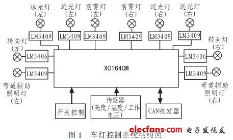
The system senses the ambient brightness and the temperature of the control board through an external sensor, and converts it into the voltage-dividing signal of the photosensitive and thermistor and the LED driving voltage-dividing signal, which is collected by the single-chip AD module.
The single chip microcomputer analyzes and classifies the digital information after AD conversion according to the pre-divided levels, and determines the current driving environment of the car (daytime, rain and fog weather, outdoor evening or late night, meeting, tunnel, etc.), and then the built-in After the feature parameters are compared and the switch is scanned, the light brightness and driving mode are automatically selected. According to the selected parameters, the corresponding PWM signal is output by XC164CM to adjust the brightness of the car lights.
The current state of the lamp can be sent to the host computer through the CAN bus interface, and the host computer can also send adjustment information to change the state of the lamp, thereby realizing the human-computer interaction function. The system structure is shown in Figure 1.
1.2 System function design
The LED lamp control system designed in this paper mainly completes the following functions.
1.2.1 Adaptive brightness adjustment
The external environment brightness is divided into 3 levels: bright (sunny outdoor, etc.), dim (outdoor rainy, outdoor evening, tunnel, parking lot and other indoor places), dark (outdoor late night or other similar occasions). The system can automatically adjust the brightness of the car lights according to the brightness level of the current environment to meet the lighting requirements in different situations. The brightness of the lamp is divided into 4 levels, 6 levels, and 8 levels of brightness, of which the level 4 is the darkest, the level 8 is the brightest, and the level 6 is centered. The adjustment strategy of the lamp brightness is as follows:
1) When the ambient brightness is increased, the brightness of the signal lamp is increased; when the ambient brightness is reduced, the brightness of the illumination lamp is increased.
2) Because it is dangerous to reduce the brightness of the lamp instantaneously, you need to make two judgments when reducing the brightness of the lamp: when the ambient brightness increases, the brightness of the lamp does not decrease immediately, but continues to wait for a period If the ambient brightness is kept at a low value and there is no change, then dim the lighting; when the ambient brightness decreases, take the same action for the signal light.
1.2.2 Status monitoring and over-temperature protection
Monitor the voltage output from the driver to the LED lamp in real time and display the result through the host computer. LED lights are defined as three states: fault state, off state, and working state. These three working states are distinguished by the current working voltage and switching state of the LED lamp. Over-temperature protection is achieved by monitoring the working temperature of the driver in real time. When the ambient temperature value of the driver exceeds 80 degrees, an over-temperature prompt signal is generated to prompt selection of the temperature control mode (drive output derating is allowed).
1.2.3 Human-computer interaction
The control system is connected with the CAN receiver of the host computer through the CAN bus interface of the XC164CM microcontroller, and realizes the interaction with the host computer information. The host computer can not only query and obtain the digital quantity of the working state of the lamp (fault state, off state or brightness level), but also send control commands to adjust the brightness of the lamp and whether to enter the intelligent lighting mode, so as to realize human-computer interaction.
2 Hardware design
The hardware is mainly composed of four parts: single chip microcomputer control module, sensor module, CAN bus module and LED drive module.
2. Brief introduction of XC164CM one-chip computer
XC164CM MCU is an enhanced 16-bit MCU produced by Infineon using low-power CMOS process. Its main features are: 1) C166SV2 core; 2) Internal integrated large-capacity memory; 3) 14 channels with self-calibration A / D converter; 4) Two comparison, capture unit, can easily generate PWM wave; 5) Twin CAN module, can exchange data through the gateway.
2.2 Sensor device
The collection of ambient brightness is done by 3 sets of brightness sensors located in different positions (front, side, top). Among them, the brightness sensor is a photoresistor GM5528 (bright resistance 10 ~ 20 kΩ, dark resistance 1 MΩ, response time 20 ~ 30 ms) installed in the photosensitive position. The temperature monitoring circuit uses a thermistor MF58 to form a voltage divider circuit, which converts the change in temperature value into a change in voltage value; the state monitoring circuit samples the output voltage of 10 LED drivers through the resistor divider network and judges the LED lamp Working status.
2. 3 CAN control module
XC164CM single chip microcomputer integrates TwinCAN module to realize CAN bus communication function. Its main features are: 1) Includes two full CAN function nodes, each CAN node is connected to the bus transceiver through a pair of receive and transmit pins, can work independently or exchange data frames and remote frames through the gateway function. 2) The transmission and reception of CAN frames follow the CAN V2.0B (acTIve) specification, and each CAN node can receive and send standard frames with 11 identifiers and extended frames with 29-bit identifiers. 3) With flexible and powerful message transmission control and error handling capabilities, CAN bus communication processing is more precise and convenient. 4) The bit timing of the 2 CAN nodes is derived from the peripheral clock, and the data rate can be programmed to 1 Mbps. 5) With 8 separate programmable interrupt nodes and FIFOs suitable for sending and receiving.
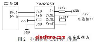
The system connects and tests the CAN communication module through the XC164CM single-chip CAN bus interface and the single-chip microcomputer development board adopting the SJA1000 controller and 82C250 transceiver to realize the human-computer interaction function. The circuit diagram is shown in Figure 2.
2.4 LED driver
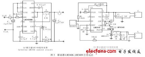
The drive module refers to the LED driving power standard of Xigong University. The signal lamp uses the LM3406 driver in the power range of 3 to 15 W, and the lighting lamp uses the LM3409 driver in the power range of 20 to 45 W.
The LM3406 driver is a buck regulator with a wide input voltage range, low reference voltage and two-conductor dimming function. It can provide a forward current of up to 1.5 A and is an ideal constant current supply source for LEDs. This chip has a built-in integration circuit to ensure the average current output. When the converter uses continuous conduction mode (CCM) operation, the controlled on-time structure can ensure that the switching frequency will remain constant regardless of the input and output voltage changes. Therefore, the output current of the LM3406 is extremely accurate and the transient response is also Very fast, it can ensure that the switching frequency is constant under different situations.
LM3409 is a step-down and steady-current P-channel MOSFET controller that provides a wide input voltage range, has a high-side current detection function, and uses an enhanced heat dissipation eMSOP-10 package. Therefore, the LM3409 is an ideal constant current source for driving LEDs, and the output forward current can be as high as 5 A. In addition, the LM3409 uses a constant off-time (COT) control function to adjust the current to ensure that the output current is constant, and does not need to provide loop compensation through external components. It can easily implement analog and PWM dimming functions, and can fully play the brightness change. And the advantages of high contrast, and provide programmable undervoltage lockout, low power consumption shutdown and thermal shutdown.
The driver structure of the signal lamp and the illuminating lamp adopt NI's LM3406 and LM3409 respectively as the BUCK circuit of the main control chip, and the chip's working temperature range is -40 + 125 ℃. The circuit principle is shown in Figure 3.
3 Software design
The program mainly adopts the interrupt control mode. The system flow mainly includes the main function, timer interrupt subroutine, and CAN receiving interrupt subroutine. The specific system flow chart is shown in Figure 4.

3.1 The main function part
1) Initialization part: Set the input and output status of each port, initialize each module and start the timer.
2) Switch scanning: 6-way switch is used to control the turn-on and turn-off of 10 lights. When the switch is closed, it outputs a low level, which corresponds to the on state of the LED lamp; when the switch is off, it outputs a high level, which corresponds to the off state of the LED lamp.
3) Status digital quantity generation: The status digital quantity is 16-bit data, the status bit (higher eight bits) indicates the drive status, and the flag bit (lower eight bits) indicates the drive number. The initial brightness of the lamp is set to 6 levels.
4) Enable global interrupt, wait for the timer interrupt signal and CAN bus communication interrupt signal, and enter the corresponding interrupt service program after receiving the interrupt signal.
3.2 Timer interrupt subroutine
The timer generates a timer interrupt signal every 20 ms and enters the timer interrupt service routine. The operations implemented in the timer interrupt service routine are:
1) Turn on AD conversion, wait for the completion of AD conversion, and normalize the AD sampling results.
2) Environmental brightness detection: To avoid misjudgment of brightness information, only when the photoresistors located in the three directions of front, side and top of the vehicle body simultaneously detect the brightness value change (and at the same time exceed the judgment threshold), the detection result is considered Effective, judge the environment brightness level, and send the result to the headlight brightness adjustment program. If the three photoresistors do not detect the change of the brightness value at the same time, it is considered that it is only the difference in brightness caused by external interference, and the brightness of the driving environment has not changed.
3) While detecting the ambient brightness, the switch quantity of the 10-way LED light is also detected and updated.
4) Adjusting the brightness of the car lights: Compare the brightness of the detected external environment with the brightness of the environment previously detected, and adjust the brightness accordingly. The specific adjustment strategy is in section 2.2.
5) Over-temperature protection: compare and judge the sampled temperature results, if the temperature exceeds 80 degrees, first generate an over-temperature prompt message, prompting the control system to enter the derating application, set the derating flag to 1, the driver power is halved, and then Reset the derating flag to zero.
6) Status digital update: First, normalize the AD sampling result, compare the conversion result of the driver voltage signal with the measured operating voltage range, and determine that it is out of range as a fault state, generate status bit 101, otherwise use The value of the brightness level register is used as the status bit. Secondly, the obtained status bit is combined with the switch register value (switch register value table: open to 1, close to 0) to get the final status bit. Finally, the status bit and the driver flag form a status digital quantity and place it in the CAN transmit buffer.
3.3 CAN receive interrupt subroutine
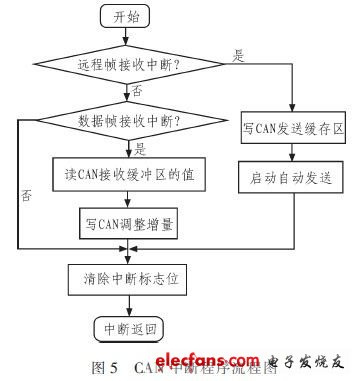
1) After the CAN bus interface correctly receives the information, set the interrupt flag bit and enter the receive interrupt service routine.
2) Determine whether the interrupt is a remote frame interrupt. If yes, write the state quantity information to the CAN module transmission buffer area and start automatic transmission; otherwise, further judge whether it is a data frame reception interrupt. If the data frame reception is interrupted, read the value of the CAN receive buffer and write it to the CAN adjustment amount. Finally, clear the corresponding flag and return to the main function. The flow chart is shown in Figure 5.
4 Conclusion
In this paper, a high-end vehicle lighting control module based on XC164CM microcontroller is designed. This module not only completes the brightness control of each vehicle lamp, but also realizes the status detection of each vehicle lamp. The working process of the car light control module is a continuous cycle of detection process. The brightness information is continuously updated by comparing the two test results before and after, and then the brightness of the lamp is adjusted according to the updated brightness information, thereby achieving adaptive adjustment of the brightness of the light . In the course of the experiment, LED5050 white light was selected as the car light experiment light, and it was equipped with a car lampshade to make a car light simulation demonstration board. The self-developed experimental circuit is connected between the lamp load and the single-chip interface, and a 6-way switch is provided on the experimental circuit to realize the control of turning on and off the 10-way lamp. The experimental results prove that the performance of the system is stable, all the functions of the design are realized, and the results can be returned correctly.
ZGAR AZ Ice Box Vape
ZGAR electronic cigarette uses high-tech R&D, food grade disposable pod device and high-quality raw material. All package designs are Original IP. Our designer team is from Hong Kong. We have very high requirements for product quality, flavors taste and packaging design. The E-liquid is imported, materials are food grade, and assembly plant is medical-grade dust-free workshops.
Our products include disposable e-cigarettes, rechargeable e-cigarettes, rechargreable disposable vape pen, and various of flavors of cigarette cartridges. From 600puffs to 5000puffs, ZGAR bar Disposable offer high-tech R&D, E-cigarette improves battery capacity, We offer various of flavors and support customization. And printing designs can be customized. We have our own professional team and competitive quotations for any OEM or ODM works.
We supply OEM rechargeable disposable vape pen,OEM disposable electronic cigarette,ODM disposable vape pen,ODM disposable electronic cigarette,OEM/ODM vape pen e-cigarette,OEM/ODM atomizer device.


ZGAR AZ ICE BOX Disposable Vape,ZGAR AZ ICE BOX disposable electronic cigarette, ZGAR AZ ice box vape ,ZGAR AZ Ice Box E-cig,AZ ICE BOX disposable electronic cigarette
Zgar International (M) SDN BHD , https://www.zgarvapor.com