
Design scheme of sewage treatment automatic control system based on S7-400
1 Introduction
In recent years, China's intensive large-scale modern sewage treatment plant requires more and more automation. The automatic control system of sewage treatment should have fully automatic logic control, the system can operate safely and trouble-free for a long time, and has high reliability. The automatic sewage control system described in this paper uses siemens s7-400 series, webaccess configuration software and profibus-dp field bus to build a distributed automatic control system, which improves the automation of sewage treatment and the high reliability of the system. .
2 Process
The water plant covers an area of ​​more than 1.2 million square meters. The design and processing capacity of the first phase of the project is 80,000 tons/day, and the second phase of the project will reach 120,000 tons/day. In view of the characteristics of the water quality, the water plant uses the Aubel oxidation ditch process. The process flow is shown in Figure 1.
First, the sewage from the urban sewage pipe network enters the coarse grid through the sewage inlet pipe of the water plant. In the coarse grid, relatively large suspended solids are intercepted to protect the subsequent power equipment. It is then lifted by a lift pump to increase the gravitational potential of the water so that the water can flow through the subsequent structures by gravity. The sewage then enters the fine grid and the smaller suspended solids in the fine grid are further intercepted. Then it flows into the swirling grit chamber for sand water separation. The sewage then enters the secondary treatment stage: the sewage first enters the anaerobic tank distribution well where the sewage is mixed with the activated sludge and is evenly distributed to the two anaerobic tanks where the sewage flows for approximately 6 hours and Under the action of highly active anaerobic microorganisms in the anaerobic tank, the macromolecules and refractory organic matter in the wastewater are degraded into small molecules, easily degradable organic substances (mostly methane and acetic acid), and most of the phosphorus is removed. Immediately after the sewage enters the next structure, the oxidation ditch, the oxidation ditch is the main stage of the biochemical reaction of the sewage. The sewage flows here for about 9 hours. At this time, a large amount of air is exposed to the water body by the surface aerator. Under the action of highly active aerobic microorganisms, almost all the organic matter in the sewage is further degraded, and most of the organic matter is decomposed. The nitrogen in the sewage is also mainly removed at this stage. Next, the sewage and part of the activated sludge flow into the integrated well together, and are evenly distributed into the four secondary settling tanks through the integrated well. The treated sewage and the activated sludge are separated in the secondary settling tank, and after the activated sludge reaches a certain concentration, a part of the activated sludge is pumped to the front end of the biological reaction tank and the inflowing sewage is mixed again. The other part is sent to the mud storage tank. In order to prevent the secondary release of phosphorus, the sludge is still subjected to secondary aeration, and then sent to the dehydration room for dehydration, and then sent to the factory for burying. The precipitated clean water flows into the chlorination contact tank for advanced treatment to meet the water body acceptance criteria and is finally discharged.
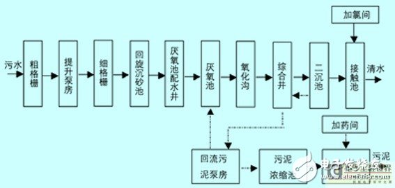
Figure 1: Process flow
3 control system design
3.1 System network structure
According to the process requirements and design requirements of the wastewater treatment plant, the system takes into account the reliability, openness, easy maintenance and scalability of the system, and adopts the distributed structure according to the principle of “centralized management and decentralized controlâ€. The water plant's automatic control system consists of a central control room, various distributed plc control stations, and field instruments and electrical control cabinets to form a three-level monitoring network. The system structure is shown in Figure 2.
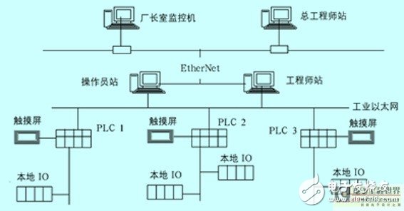
Figure 2: System Block Diagram
2 Monitoring system network structure
The control system has a total of 2 monitoring computers, one of which is reserved. There are also 3 plc control master stations. The control master station is connected to the upper engineer station of the central control room via the fieldbus for easy monitoring. The computer of the upper engineer station, the operator station, the chief engineer station and the director's office is connected to the Ethernet, and the management machine completes various management functions. In this way, the entire automated monitoring system constitutes the scada remote monitoring system, which realizes functions such as data acquisition, processing, monitoring and control of field devices.
3.2 Control method
The main process equipment in the system uses three control modes, namely local manual control, remote plc control and automatic control. Switch signals such as pumps, surface aerators and equipment on and off, and analog signals of various structures (such as do, tp, ph, tss, etc.) are all displayed on the host computer via plc. The physical parameters of each monitoring point on the site are connected to the plc main station via the profibus bus.
3.3 System function design
(1) The function of the host computer monitoring system. The host computer uses two Advantech industrial control computers connected to the on-site plc main station via Industrial Ethernet. The upper computer operating system adopts windows xp, and the monitoring software uses webaccess. The main function of the upper computer is to collect the data of the sewage treatment plant; set the parameters of the automatic control system; complete the configuration of the control system, and at the same time Perform online and offline programming and modification of setting parameters; monitor the production process through the displayed control process screen and real-time data; perform statistical analysis and storage of historical data and complete report printing. In addition, inte-rnet is connected in the factory LAN, which realizes the remote field device monitoring function of the local area network, local network and remote network. In this way, the manager can obtain the information of the water plant through various internet access methods anytime and anywhere, and expand the scope to the factory monitoring level, realizing the combination of the upper information network and the control network.
(2) Unit control station. According to the requirements of the process, there are 3 unit control stations in the whole plant, which are plc1 station, plc2 station and plc3 station. The unit control station selects cpu414-3dp for the plc.cpu of simaTIc s7-400 series. The cpu has medium performance and is suitable for occasions with high program size, command processing speed and communication requirements. It has an mpi/dp interface, a dp interface, and a profinet interface. The distributed i/o point addresses assigned to the dp interface and the profinet interface are respectively 8 kb. The unit control station performs parameter detection on the site and the device operates. The signal is collected, detected and controlled, and the device can be operated through the man-machine interface of the station, and the data is transmitted in real time to the upper computer system. The control parameters set by the host computer system are transmitted to the unit control station through the fiber optic Ethernet, and then the unit control station completes the control of the field device. The unit control station also monitors its own templates, and its diagnostic system continuously monitors the functions of the system and process, recording errors and specific system events. If a diagnostic message event occurs, the template will trigger a diagnostic interrupt, after which the unit control station interrupts the execution of the user program and executes the corresponding diagnostic interrupt module.
Rubber Bar Mat,Rubber Beer Mats,Bar Service Mat,Rubber Drip Mat
Cixi Mingsheng Rubber & Plastic Co.,Ltd. , https://www.popmat.com