
Application Status and Development Trend of Frequency Conversion Control Technology in Air Conditioning (1)
1 Introduction With the gradual popularization of inverter air conditioners, the seasonal energy efficiency ratio (SEER) of air conditioners has been continuously improved, and low-efficiency air conditioners have been gradually eliminated; at the same time, people have gradually experienced and pursued the high comfort of inverter air conditioners, making inverter air conditioners Further play an unparalleled advantage.
This paper briefly introduces the speed control technology of compressors, indoor and outdoor fans in inverter air conditioners, and forecasts the further development trend of frequency conversion control technology for air conditioning systems.
2 Current Status of Air-Conditioning Frequency Conversion Technology In air-conditioning systems, motors that require variable speed control are mainly compressors, outdoor fans, and indoor fans. These motors are the main control objects in variable frequency air conditioning systems. The current status of variable speed control technology is roughly as follows.
2.1 Variable Speed ​​Control of Air Conditioner Compressor Variable speed control technology for air-conditioning compressors is roughly divided into the following stages.
(1) Before 2005, AC frequency conversion was mainly based on AC variable frequency speed control technology, that is, the compressor motor was an ordinary AC induction asynchronous motor, and its rotation speed was n=60*f*(1-S)/p(1).
Where: f---AC power; S---slip; p---pole pair.
It can be seen that the synchronous speed of the induction motor is proportional to the power supply frequency. If the frequency of the AC power supply changes, the synchronous speed of the induction motor can be changed. The “inverter air conditioner†is therefore named after the variable frequency speed control technology.
AC variable frequency air conditioners usually control the compressor in variable voltage (VVVF) mode of “AC→DC→AC†mode. The VVVF control signal is generated by a single-chip microcomputer processor (MCU) to generate a sinusoidal pulse width modulation (SPWM) signal to control a three-phase inverter bridge, and an intelligent power module (IPM) is generally selected to generate the SPWM AC frequency conversion. The voltage generates a sine-wave current through the inductance of the windings in the AC induction motor and the operation of the induction motor. According to the characteristic of the AC motor, when the required torque is constant, the voltage between the three-phase lines of the induction motor must be increased as the frequency increases. Therefore, while the VF is changing the frequency, the VV variable voltage function is also realized by adjusting the pulse width. Different compressors have different VF curves, so the VF curve should be set according to the characteristics of the compressor.
The circuit diagram of the AC inverter air conditioner controller is shown in Figure 21. 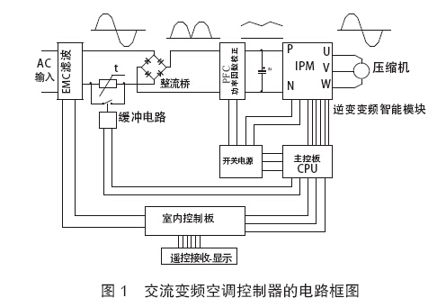
SPWM waveform generation principle and IPM output waveform diagram shown in Figure 2, is a three-phase bipolar modulation SPWM wave. 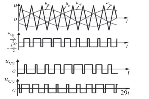
Figure 2 SPWM waveform generation principle and schematic
However, AC induction motors are less efficient and the load characteristics of the compressor are very special: the torque at each corner varies greatly with each revolution. Therefore, although the AC inverter air conditioner can greatly improve the seasonal energy efficiency ratio than the fixed frequency air conditioner, its narrow speed range, large noise and vibration, low motor power factor and energy efficiency ratio is inferior to DC variable speed, etc., and is gradually changed by the DC speed. Technology was eliminated.
(2) From 2004 to 2009, the 120-degree square-wave era gradually promoted the DC variable-speed technology, that is, the compressor motor was switched to a brushless DC (BLDC) motor, and it was mainly driven by a 120-degree square-wave method. BLDC motor sectional structure diagram, as shown in Figure 3.
The key to driving a DC motor is synchronous commutation. After switching to brushless, commutation is usually accomplished with three-phase input and IPM. The main circuit of the DC speed change is almost the same as the AC frequency conversion control circuit. In order to meet the synchronous commutation, the rotor position of the BLDC motor generally needs to be known. At present, the magnetic effect of the Hall element is often used to realize the detection of the rotor position, as shown in FIG. 4 . The commutation method of the three-phase IPM is based on the position of the rotor. The two phases turn on in turn, and the magnetic poles of the rotor are sucked and continuously rotated. Because the three phases are two-phase turn-on conduction, they are also called “120° square wave driveâ€, in which 60° is the cutoff of both the upper and lower arms. The theoretical waveform of the output voltage of a certain phase is shown in Fig. 5.
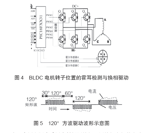
Since household air conditioners use fully-enclosed compressors, the electrical connection lines of the compressor motor must use a process of sealing and high-voltage insulation. The fewer electrical connectors are, the better. Therefore, using a sensorless BLDC motor requires only 3 electrical connectors. Its rotor position detection is obtained using the back EMF detection method. Back electromotive force means that when the three-phase commutator of the controller has no output, the rotor of the BLDC motor has no external current in a moment and only depends on the inertia, and this moment becomes a local three-phase sinusoidal voltage output by the generator. The sinusoidal phase angle corresponds to the angle of the rotor. The actual back-EMF detection is performed at the above-mentioned period of 60° and the upper and lower arms.
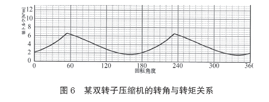
The MCU performs accurate commutation of the three-phase inverter bridge in time according to the position signal. As the load of each corner of the compressor changes greatly, as shown in Fig. 6, under the knowledge of the position of the rotor, the MCU can intentionally increase the PWM pulse at some corners where the load is large through the actual load characteristics of the compressor. Width to increase torque in this corner area. This method of artificially compensating the torque is called "torque compensation", thereby greatly improving the low-speed driving performance of the compressor and reducing the vibration.
The constant speed control of the BLDC motor driven by 120° square wave is achieved through a speed closed-loop method. That is, the speed pulse signal is obtained through the back-EMF rotor position detection signal. The MCU compares the pulse speed signal with the set rotation speed and adjusts the PWM pulse width. The actual speed is close to the set speed. This type of passive control of the closed loop of a large loop can easily cause speed fluctuations.
The disadvantage of the 120° square-wave drive BLDC compressor is that the two-phase wheel flow electric drive affects the efficiency and torque stability, the torque compensation is artificially controlled by the software personnel, and the speed is only related to the voltage (pulse width control) and the load. Causes the speed to fluctuate when the PID is adjusted improperly.
(3) After 2008, the 180° sine wave era gradually promoted and popularized the 180° sine wave driving BLDC compressor technology, especially the standard implementation of energy-efficient inverter air conditioners in recent years. AC frequency conversion and 120° square-wave drive compressors are almost All were eliminated.
The 180° sine wave is called relative to the above 120° square wave. In fact, it is a vector control method that automatically estimates the rotor position and load of a BLDC motor based on the output current sampling of the compressor motor and the current change trend, so that the torque under different loads can be automatically adjusted at any rotation angle. . At any moment, the three-phase stator windings have current and at the same time generate suction or thrust on the rotor. Therefore, the 180-degree sine wave can overcome the above-mentioned deficiencies of the 120-degree square-wave drive mode, so that the compressor has the highest motor efficiency and the most balanced operation. With less noise and vibration.
DC vector algorithm based on DC voltage sampling and current sampling data processing, schematic and vector control block diagram shown in Figure 7, vector control and voltage waveform shown in Figure 8.
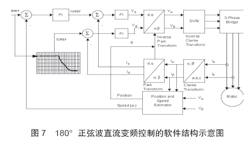
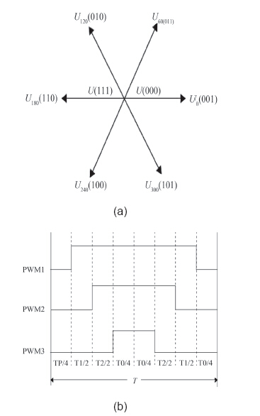
Fig. 8 Vector control (a) and voltage waveform diagram (b)
180 ° sine wave DC inverter not only three-phase power and sine wave torque continuous and stable, but also voltage and current double closed-loop control mode. Therefore, its high efficiency, small vibration, fast response, automatic adjustment ability, control characteristics is significantly better than 120 ° square wave. In particular, the speed control becomes active control, and the speed stability can be greatly improved.
It is worth mentioning that although the torque of the vector control can be automatically adjusted and adapted, when the torque of the phase angle of the load changes too much, the torque of the phase angle can be artificially increased to achieve over-compensation or active compensation. With a reasonable parameter adjustment, a smooth operation of the compressor at very low rotational speeds can be achieved. This is critical to the comfort control of inverter air conditioners. At present, most inverter air conditioners of air conditioner companies have chosen this 180-degree sine wave control method.
2.2 Speed ​​Control and Steady Speed ​​Technology of Air Conditioning Outdoor Fans When the indoor temperature is close to the set temperature or the ambient temperature is not very high, the inverter compressor is mostly operated at low speed. At this time, the electric power is very low. If the outdoor fan at this time still uses a single-speed fan, the power consumption of the fan is usually equivalent to that of the compressor and even exceeds the power consumption of the compressor, thus seriously affecting the required SEER index. At the same time, if all the air-conditioner fans in a building group are operating at the maximum speed, the environmental noise should not be underestimated. Therefore, unless the low-frequency fixed-frequency air conditioning, the general season of high efficiency (SEER) inverter air conditioner, without exception, use variable speed outdoor fan.
The speed regulation technology of outdoor fans is roughly classified into the following categories: Tapped AC induction speed control fans, two-way thyristor phase-controlled speed control fans, square-wave BLDC fans with Hall sensors, and position-sensorless BLDC fans.
(1) Tap-type AC induction speed control fan This type of fan is based on common capacitive single-phase AC induction asynchronous motors. The number of windings and inductance of the main winding are changed through tapping of the stator main winding to control the input current and output torque of the motor. To achieve speed adjustment.
When the tap is in the H position where the number of turns of the main winding is small and the inductance is small, the input current is large, and the output torque of the motor is relatively close to the synchronous rotation speed. At this time, it is a "high wind zone"; when the tap is in the main winding turns, In the multi-L position, the inductance of the main winding increases so much that the input current decreases, and the output torque also decreases. At this time, the slip ratio S increases and the rotation speed n decreases, which is a “low wind zoneâ€; The tap is located at the M position between the two, which is the "stroke zone." Some air conditioners only have two wind speed zones, and there is no tap position for the "stroke zone" M. Tap-type speed control fan schematic shown in Figure 9.

This type of fan-type fan is usually achieved through the switching of the relay.
Tapped fan slip ratio S is determined by the size of the motor current/torque and the size of the load. That is to say, the speed of the tapped speed governor fan can only be adjusted in steps, when the input voltage fluctuates and changes greatly. The controller MCU needs to sample according to the condenser temperature to switch between high and low winds. For example, when the input voltage is very low, the original setting is in the “stroke†position, but when the MCU detects that the condenser temperature is high, the control should be switched to the “high wind†position.
Although the tap-type fan is simple and inexpensive to control, the greater the slip ratio S, the lower its efficiency. Therefore, although the rotational speed is low at low power, the power consumption of the fan can not be underestimated. Therefore, it is only applicable to low-cost and low-efficiency air conditioners.
(2) Built-in 120° square-wave BLDC fan technology with Hall-position sensor The structure of the BLDC fan is shown in Figure 3, and the inverse-phase control circuit is shown in Figure 4. The difference is that due to the large fan blades of outdoor fans, the rotational speed is not high. Therefore, the number of motor pole pairs is large.
The biggest advantage of the fan that replaces the phase power device is that the Hall device can be directly mounted on the drive phase change plate, the rotor position detection is accurate, and the internal displacement phase is integrated with the motor. Not only less interference, less connection, but also accurate output speed signal, convenient control, very popular with air conditioning controller designers.
Built-in BLDC fan control is relatively simple, generally need to provide DC power supply Vm, voltage between DC300V±100V; also need to provide 15V working voltage Vcc, speed control voltage Vsp, they share a Com terminal (DC-). As mentioned before, in order to achieve the steady speed of BLDC fans, such fans have a speed signal, which is generally 12 pulses/rev. In this way, a 5-core wire is connected to the controller. 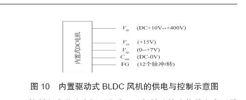
The control method is a speed closed-loop method, and the general speed output signal is realized by a built-in Hall device, which is generally 12 pulses/rotation. The MCU compares the set speed with the actual feedback speed, and realizes speed closed loop by outputting PWM or adjusting Vsp. Although the cost of the BLDC fan is high, when the fan speed is very low, the power consumption can be as low as several W, so it is particularly suitable for high SEER energy efficiency models. The built-in fan also needs to consider the heat of the built-in power device. Generally, the fan power does not exceed 100W.
(3) External BLDC Fanless Technology without Position Sensor When the fan power exceeds 100W, the built-in three-phase inverter-phase power device (IGBT or MOSFET) does not easily dissipate heat, which may cause the built-in power device to be overheated and damaged. At this time, unless there is a special heat dissipation design, priority should be given to the external reverse-conversion phase controller to drive the BLDC fan.
The simple external type still uses the Hall position sensor and the 120° square wave to drive the BLDC fan technology. The disadvantage is that the number of Hall sensors connected is large. Generally, three Hall signal sensors are required to connect the cable, and one rotation speed signal line is required. And two 5V positive and negative power lines, plus three BLDC thick links, at least more than 10 lines; when the air conditioning controller and BLDC fan far away, it is easy to produce interference signals on the sensor signal line, so that The BLDC control is disturbed, and from the viewpoint of safety isolation, the three BLDC rough wires are preferably split/isolated from the speed position signal line, which is also a method that has not been widely promoted.
Therefore, the current state-of-the-art technology is the same as the compressor, and it also uses a position sensorless BLDC motor and uses a sinusoidal-wave DC vector control method of 180°. This method has been described in detail before, and the technical principle will not be repeated.
The difference between a BLDC fan and a compressor is that the rotor blades have a much larger moment of inertia than the compressor and must be considered for start-up problems during upwinding. That is, when the wind is turned against the wind, the airfoil rotates in the reverse direction. If it is not possible to perform braking and initial positioning of the rotor at this time, it is difficult to achieve synchronized start. This is also a big challenge for the position sensorless BLDC fan control.
2.3 Speed ​​Control and Steady Speed ​​Technology of Indoor Air-conditioner of Indoor Air-conditioner The speed control technology of indoor air-conditioner is directly related to energy efficiency and comfort of the room air conditioner.
From the consideration of cost and technical complexity, the most widely used is the two-phase SCR phase-controlled AC fan technology. For high-power wall-hangers, high-end models are gradually adopting built-in 120° square-wave BLDC fan technology with Hall-effect position sensors to further increase energy efficiency. For indoor fans with large power, such as top blower, ceiling blower, imitation air blower, and locker, the control method is similar to that of outdoor fans. Low-end machines use tapped AC induction fans, and high-end machines use BLDC fans. Then repeat them.
The following focuses on the most common two-phase SCR phase-controlled speed control.
(1) Two-phase thyristor phase-controlled AC fan technology From the above, it can be seen that the frequency conversion speed control technology of AC induction motors is complex and the cost is high. Therefore, for the stepless speed regulation of indoor fans of small-power room air conditioners, a two-phase thyristor phase-controlled speed regulation technology with a simple structure and lower cost is generally used.
The AC induction motor has the same speed equation as the previous formula (1). In addition to adjusting the frequency to change the speed, speed can also be achieved by changing the slip rate S. Of course, the speed regulation method of adjusting the S is very inefficient and the power factor is very low, and it is only suitable for the high speed of the low-power indoor fan.
The basic principle of phase-controlled speed control of two-way SCR is actually changing the duty ratio of the power frequency voltage (similar to the pulse width of the PWM) by adjusting the conduction angle of the thyristor so that the current flowing through the induction motor changes. Achieve the change of the slip S of the asynchronous motor.
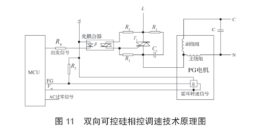
Like all phase control technologies, this phase-controlled speed control method also has a zero-crossing signal of the AC frequency of the power frequency. The zero-cross signal is sent to the MCU interrupt port of the indoor controller. At the same time, the speed pulse signal of the fan is sent to the MCU. . In the initial stage of startup, the MCU first gives an initial conduction angle, the triac conducts at the initial conduction angle, first outputs an initial duty cycle voltage, and compares the actual speed after the fan is running and the set speed. Depending on the difference, the PID adjustment of the conduction angle of the triac is performed until the actual speed is consistent with the set speed.
Two-way thyristor AC voltage regulator type fan, because with the speed feedback signal FG, often referred to as PG fan.
PG fans are generally only suitable for low-power 1HP-1.5HP wall-mounted air conditioner indoor units because of their low efficiency. Not only widely used in inverter air conditioners, but also widely used in fixed frequency wall mounted air conditioners.
(2) Other indoor fan control technologies Air-conditioner indoor fans, depending on the type and power size, are mostly similar to outdoor fans. In addition to low-power wall-mounted machines, SCR-phased pressure-regulating and speed-regulating PG fans are used, such as vertical machines, ceiling machines, top-out fans, and imitating duct machines, etc. AC fan speed control. In recent years, some high-end models have just started to use BLDC fans with 120° square-wave drive with a Hall sensor and BLDC fans with 180° sine-wave DC vector control.
These three control methods are exactly the same as those of outdoor fans and will not be repeated here. The difference is that the wind blades are different, and the majority of outdoor fans use axial fans with a large amount of air; while the indoor fans have more centrifugal or tuyeres with high pressure and low noise, and their relative rotational speed is also lower.
About the Author Li Shangen (1949-), male, Ningbo, Zhejiang, senior engineer, chief engineer of Hangzhou Pioneer Electronics/Sanhua controller R&D center, research direction: inverter air conditioner controller technology.
Applications:
The use of a K-rated transformer is anywhere non-linear loads are present. Prime uses would be in factory automation, computer rooms, and office buildings because of the high harmonic content in these areas, Typically a K-13 rated transformer is sufficient for most applications. UL recognizes K-factor values of 4, 9, 13, 20, 30, 40 and 50. The K-factor number tells us how much a transformer must be de-rated to handle a definite non-linear load or, conversely, how much it must be oversized to handle the same load.
How to choose your K factor transformer?
K1: standard transformers, standard lighting, motors.
K4: Induction heater, SCR, AC drive
K13: School pulse lighting, hospital
K20: Data processing computer, computer room.
Or send your requirement to SCOTECH!
Why SCOTECH
Long history- Focus on transformer manufacturing since 1934.
Technical support – 134 engineers stand by for you 24/7.
Manufacturing-advanced production and testing equipment, strict QA system.
Perfect service-The complete customer service package (from quotation to energization).
K Rated Transformer,K4 Rated Transformer,K13 Rated Transformer,K Factor Power Transformer
Jiangshan Scotech Electrical Co.,Ltd , https://www.scotech.com