
Quantify the effects of radio frequency (RF) interference on linear circuits
A typical precision operational amplifier (op amp) can have a gain bandwidth product of 1 MHz. In theory, users may expect RF signals at the gigahertz level to decay to very low levels because they are well beyond the bandwidth of the amplifier. However, this is not the case. In fact, electrostatic discharge (ESD) diodes, input structures, and other non-linear components contained within the amplifier "rectify" the RF signal at the input of the amplifier. In a practical sense, the RF signal is converted to a direct current (DC) offset voltage that adds the amplifier input offset voltage.
The user may ask: “How do I determine the magnitude of the DC offset voltage generated by a given RF signal?†In fact, the sensitivity of the amplifier to RF interference depends on the design and technology used in the amplifier. For example, many modern amplifiers have built-in RF filters to minimize the chance of this problem. This filter is most effective for low gain bandwidth op amps because the filter's cutoff frequency can be set to a lower frequency, which provides a higher RF signal attenuation factor. In addition, some technology products have stronger inherent RF immunity. For example, most complementary metal oxide semiconductor (CMOS) devices have greater resistance to RF interference than bipolar devices. Other factors such as input stage design can also affect the ability to resist RF interference.
With all of these factors in mind, how should board and system level designers choose an amplifier? The answer is: look at the electromagnetic interference suppression ratio (EMIRR). This specification is similar to the power supply rejection ratio and the common mode rejection ratio because it converts the effects of RF interference into DC offset voltage at the input of the amplifier. As an example, Figure 1 shows the EMIRR curve for the OPA333. It can be noted from the curve that the op amp has an EMIRR of 120 dB when the frequency is 1000 MHz. This is a very high level of suppression, making it possible to directly compare this curve with the curves of other devices.
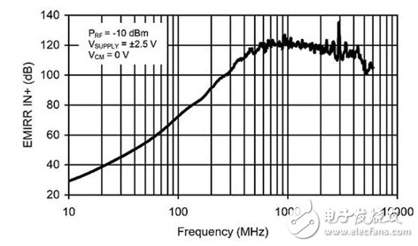
figure 1
Frequency (MHz)
Example of EMIRRIN + compared to frequency when using OPA333
The EMIRR curve shows the measured value of the interference capability of the op amp's conducted anti-RF signal, which is applied to the non-inverting input. The term "conducted" means that the RF signal is applied directly to an op amp input using an impedance matching printed circuit board (PCB). In addition, the reflection at the input of the amplifier is characterized and illustrated.
Finally, the DC offset voltage generated by the RF signal is measured with a digital multimeter. Note that a low pass filter is used between the amplifier and the multimeter to prevent potential errors caused by residual RF signals passing through the amplifier. Figure 2 shows the test circuit used to characterize the EMIRR.
figure 2
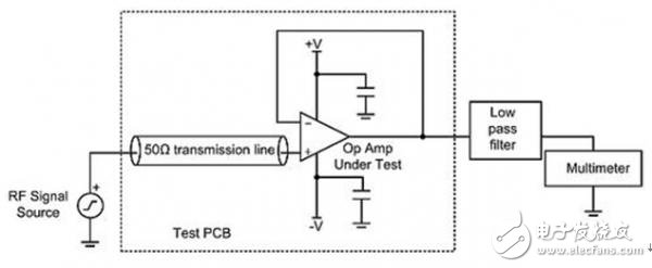
Test circuit for characterizing EMIRR
Equations (1) and (2) give the mathematical definition of EMIRR. The two equations are reset versions of each other. Equation (1) shows the relationship between the RF signal used and the change in the offset voltage. Note the offset voltage change caused by the square of the RF signal used. This means that a small increase in the incident RF signal can result in a significant increase in the offset voltage. Also note that the term EMIRR acts to attenuate the effects of the RF signal; in other words, a larger EMIRR (dB) can significantly reduce the variation in the offset voltage. Equation (2) is an equation form used to calculate EMIRR (dB) during the characterization process.
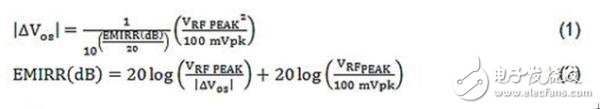
among them
EMIRR (dB) - The EMI rejection ratio (in dB) measured from the conducted RF signal is applied to the input of the non-inverting amplifier
|△Vos|——is the measured offset voltage (caused by RF interference)
VRF_PEAK - is the peak RF interference applied to the non-inverting input of the amplifier
Finally, please note that many other factors, such as PCB layout and shielding, can also affect the RF immunity of your system. However, once these factors are optimized in the user's design, the best performance can be achieved with an amplifier with good EMIRR. Moreover, the user does not need to perform any complicated calculations. Simply compare the EMIRR curves of the different amplifiers to select the device that best suits your application. I hope that users can use the EMIRR specification to optimize the user system's ability to resist RF signal interference.
GreenTouch infrared touch screen uses the high quality of transparent glass so it has excellent clarity, resolution, light transmittance and reliability. Even though there are some scratches on the surface of glass,it can still work normally. The surface of the screen has no surface coating on the plastic film or moving parts, so there is no parts will wear consumption during the usage.infrared touchscreen ensures stable performance without any ghost spots or drift.The operation is sensitive, through finger, glove, passive stylus and other opaque objects can perform accurate touch input. a high-precision IR Touch Screen.
Pictures show:


Multi Point Infrared Touch Screen,Smart ​Infrared Touch Screen,Infrared Touch Frame Technology,Touch Screen Frame For Tv,Infrared Touch Screen Panel,IR Touch Screen
ShenZhen GreenTouch Technology Co.,Ltd , https://www.bbstouch.com