
Design of Dynamic Smart Home System Based on Zynq Platform
Abstract: Due to the fixed location of sensors in traditional smart home wireless sensor networks, the number of network nodes that need to be arranged is too high, resulting in high cost. In view of the above reasons, in order to achieve the goal of capturing the information required by users in real time under the premise of reducing Zigbee network nodes, this paper proposes a dynamic intelligent home system based on Zynq-based FPGA chip: the system uses smart car as mobile gateway. Zigbee acts as a network node and uses the Sim300 GSM module to implement SMS messaging. The remote user can obtain the information in the home in real time; and can communicate with the smart home gateway by using SMS and the Internet, thereby realizing remote control of the smart home system.
With the development of computer technology, information technology, control technology, and the continuous improvement of people's material living standards, traditional houses have obviously failed to meet people's needs, and smart homes have emerged. A true smart home sensor network can connect all items to the 3G Internet through RFID and other information sensing devices for intelligent identification and management. In addition to the functions of traditional home system sensor data acquisition, analysis and security alarm, and mobile phone SMS remote control of household appliances switch, the dynamic smart home system studied in this paper can obtain home information in real time by adding the mobile intelligent gateway. . Remote communication with the smart home system through SMS and Internet communication with the smart home gateway.

1.1 System Research Background Currently, embedded design is developing rapidly, and the demand for high-performance, low-power, high-flexibility processors in scenarios involving a large number of data processing modules (such as intelligent video surveillance, advanced industrial control, etc.) Very high, the existing microprocessor lacks sufficient signal processing capability, and the Zynq-7000 is a high performance and low power processor platform with ARM+FPGA architecture that provides flexible and scalable solutions. Program.
The traditional smart home system main control CPU generally adopts ARM+Zigbee solution. In this system, Zedboard FPGA (field programmable logic gate array) is used as the main control CPU, Zigbee module adopts CC2530 Soc solution, GPRS module. The sim300 module is used to interact with the user's mobile phone using the AT command, and the Internet interaction is realized by BOA and CGI. The FPGA implements the PWM signal to generate a logic control motor.
1.2 System implementation architecture As shown in Figure 1, the main control module completes the functions including Zigbee coordinator, GSM/GPRS, Internet interconnection, camera video acquisition and motor drive car control. The module contains two processes, the process is responsible for The Zigbee network data is taken, and the processed data is distributed to the GSM/GPRS module and the Internet WebServer module.
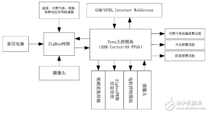
Figure 1 system hardware structure framework
The process one further includes three independent threads, which interact with each module respectively. The flow is as follows: pthread_t TId[3]; //Create thread number pthread_attr_t attr[3]; // allocate space for thread pthread_attr_init(&attr[0]) ; pthread_attr_setscope(&attr[0], PTHREAD_SCOPE_SYSTEM); ....... //Thread space initialization pthread_create(&TId[0],&attr[0],thread_serial_ttyPS1,NULL); //Create thread 1: for ZedBoard acquisition ZigBee network data pthread_create (&TId[1], &attr[1], thread_serial_uartlite_debug, NULL); / / create thread 2: used for ZedBoard to send packets to GSM pthread_create (&TId[2], &attr[2], thread_serial_ttyPS1toWeb, NULL) ;//Create thread 3: used for ZedBoard to send data packets to the Internet pthread_join(tid[0], NULL);....... //Add thread pthread_rwlock_destroy(&GPacketBuf_rwmutex) to the main function; //release thread
The second process is the CGI module, which is called by the WebServer. Its functions include parsing the data packet and presenting the ZigBee information to the user in the form of a web page. The process is as follows: the first step is to create a data packet format, and the second step is to use the HTML language. The temperature sensor, battery supply voltage, fire warning, burglar alarm, fan, and light switch status collected by Zigbee's self-organizing network inform the user through the webpage. Users can log in to the Internet to view the complete information of the home status. The specific format of the data packet will be Will be given at the back of the ZigBee module.
2 ZigBee ad hoc network2.1 ZigBee network node configuration There are three kinds of devices in the ZigBee network: Coordinator: responsible for starting the entire network, it is also the first device of the network. The function of the router is mainly: Allow other devices to join the network and assist themselves as terminal devices at the same time. Communication. The terminal device has no specific responsibility for maintaining the network structure, it can sleep or be woken up.
2.2 Serial Communication Packet Format
The ZedBoard master and Zigebee coordinator communication packet format is as follows: StartByte -> 1B (representing the packet start byte 0x47) PropertyId -> 1B (representing the attribute ID) NodeId -> 1B (representing the Zigbee terminal device node ID) PacketLength- > 2B (representative of the length of the packet) PrivateData-> XB (on behalf of the content attribute ID corresponding to the load X = PacketLength -6) EndByte-> 1B (on behalf of the end byte packet 0x48)
The uniform format of the data packet is not only used for communication between the ZigBee coordinator node and the ZedBoard, but also for the data packets sent by the ZedBoard FPGA development board to the serial communication between the GSM modules, and also for the data packets transmitted by the ZedBoard to the Internet CGI module. That is, the three data packets are unified. Then the receiving module parses the received message through the data packet protocol. The GSM module will judge whether there is a warning condition by parsing, and then send a text message to the user to warn, and the Internet module will then The data collected by the sensor is displayed as text on the web page.
2.3 Motor drive and smart car implementation The module is realized by L298N double H-bridge DC motor drive module. The power supply range of the drive part is Vs +5V to +30V, and the peak current of the drive part is 2A. The schematic diagram is shown in Figure 2 below. In the figure, IN1, IN2, IN3, and IN4 are control signals. When IN1 is 0 and IN2 is 1, motor a is rotating forward, IN1 is 1, and when IN2 is 0, motor a is reversed. When IN1 and IN2 are both 0 or 1 at the same time, the motor stops rotating. PWM-a and PWM-b are the enable terminals, and the FPGA PWM output signals are connected. L298N-a and L298N-b are the output terminals of motor A. Motor b The principle is the same as above. The DC motor drive is mainly used to drive the smart car to realize the movement of the car in the room, and use the camera to collect the real-time information of the room and return it to the user through the Internet in time; in addition, the smart car also has a ZigBee module with a heat release. An electric human body infrared sensor detects whether a stranger enters or exits the room, and the flammable gas sensor detects whether a flammable gas leaks in the kitchen, and the smoke sensor detects whether a fire has occurred.
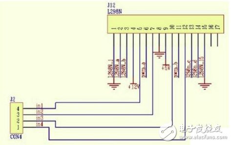
Figure 2 DC motor drive schematic
2.4 GPRS/GSM module In the GPRS module, we use the SIM300 development module provided by Simcom, mainly to use the 8051 single-chip microcomputer to realize data analysis to determine whether there is a warning message, and then send a warning message to the user, and send a text message to the user. The serial port of the single chip computer transmits a series of AT commands to the serial port of SIM300 to realize.
In the process of sending the AT command, it is found through experiments that the frequency of sending the AT command is too high, which will cause the SIM300 to react but cause the operation to fail. If the transmission frequency is too low, the real-time information will be missing, and the user cannot know the warning information in time. And by sending short-term interest to control, GPRS as a medium to achieve user and smart home system interoperability. Similarly, the Internet side also serves as an intermediate medium to achieve user control of smart cars. The goal of realizing dynamic browsing. The flow chart of specific communication is shown in Figure 3 below:
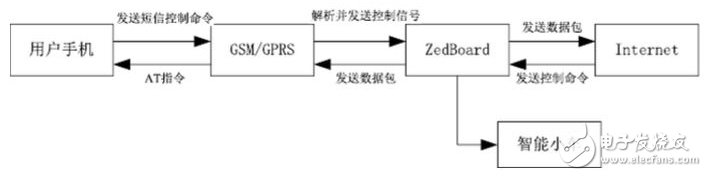
Figure 3 Schematic diagram of information transmission between modules in the system
3 Conclusion(1) Using the embedded high-performance processor ZedBoard as the main control CPU, using the Linux software platform to implement complex application logic: for example, defining communication protocols, collecting and distributing information, and defining Uart IP cores, not only improves the development cycle, but also facilitates Later expansion; and the overall function of the system is relatively stable.
(2) In terms of serial communication, the experiment found that the packet loss phenomenon is serious at high baud rate, and the low baud rate will cause the information feedback to be untimely, resulting in a decrease in the real-time performance of the system. The rate is set to 9600.
(3) By introducing a smart car, the video information collected by the mobile car can be transmitted to the Internet in time. The next step is to analyze the relationship between the serial port data rate and the effectiveness of the MMS transmission, research and optimize the MMS transmission strategy, and strive to realize real-time monitoring of the Internet. At the same time, when the SMS sends an alarm signal, the GPRS module can timely feed the picture to the user in the form of a multimedia message.
references
[1] Lu Jiahua, Jiang Zhou, Ma Wei. Practical Guide for Software and Hardware Cooperative Design of Embedded Systems-Based on Xilinx Zynq. Beijing [M]: Mechanical Industry Press, 2012: 12-14, 272-287.
[2] Feng Chengjin. Research and design of smart home system based on Zigbee and ARM9 [Master's thesis]. Wuhan University of Technology. 2010: 5-8.
[3] Wu Wenzhong, Li Wanlei. Intelligent home system based on ARM and ZigBee[J]. Computer Engineering and Design, 2011(06): 1987-1990
[4] Yuan Yuan, Wang Ziting, Liu Yangfan. Smart Home System Based on FPGA and ZigBee Technology[J].Information Communication,2011(06):42-43.
other
other
AST Industry Co.,LTD , https://www.astsoundchip.com