DSP realizes bionic machine crab multi-joint control system
The bionic robot crab control system requires high control precision and calculation speed, so as to ensure the normal walking and attitude control of the robot by increasing the response speed in the case of high mechanical rigidity. Since there are two motors (shown in Figure 1) in the robot crab leg section and the shackles, the mass is large, and the walking distance of the walking feet is small due to the limitation of the volume, so the robot crab will be in the walking process. The middle coupling is strong, and the control model is greatly influenced by factors such as body posture, walking foot shape and gait. This requires the control system to have a flexible control structure, the ability to adjust the walking foot trajectory and gait, and adapt to changes in the control model. Therefore, it is necessary to develop a robot crab control system with powerful arithmetic processing capability and modular software and hardware structure.

From the perspective of operational tasks, the main design purpose of the amphibious bionic robot crab is to be used for future amphibious military reconnaissance. Therefore, it requires autonomy and intelligence, and should design the embedded control framework from the practical point of view. The design goals of the control system are: (1) fast and accurate position control for each joint; (2) coordination of movement between the joints of the walking foot and movement of each walking foot to achieve the desired target trajectory; (3) real-time Collect and process sensor data for use in signal synthesis of control systems; (4) Implement robot gait planning, motion equation solving, and fast transfer of control commands; (5) have good control structure and interface for easy Development of high-level control software; (6) has a certain reserved interface, good compatibility and scalability for functional expansion and secondary development and research; (7) has a modular structure to adjust the number of walking feet, Suitable for control in the form of asynchronous states.

1 Multi-layer multi-objective distributed control concept and control framework Bionic robot crab is a complex control object. From the system, each walking foot is a multi-degree-of-freedom series arm robot. In order to achieve effective control, in addition to accurate and efficient control of each of the three driving joints of each walking foot, multiple walking feet must coordinate with each other to complete a certain determination. At the same time, the strong coupling formed by mutual overlap and mutual interference between the walking foot motion spaces should be considered.
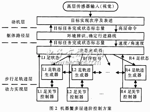
Commonly used control methods include decentralized control, distributed control, and hierarchical control. Because the hierarchical control system has the characteristics of clear control structure and clear hierarchy, and the distributed control system is easy to adopt modular structure and has good expandability, the control system design of the robot crab control system adopts combination of hierarchical control and distributed control. . Because of its complicated control structure, the whole control system is divided into multi-layer structure such as task planning, task decomposition, body path planning, motion coordination, walking foot trajectory planning, kinematics/dynamics calculation, motor servo control, and each layer. Coordination between the upper layers, such as the coordination of motion control between the walking feet, requires the walking foot control layer to exchange information through the walking movement coordination layer. The same is true for the control between the knuckles of each walking foot. Therefore, the machine crab control system uses a multi-layer multi-objective distributed hierarchical control system, as shown in Figure 2.
The first layer is called the “motivation layerâ€, which enables the robot body to be completely autonomous. The purpose is to translate the internal response of the ontology caused by external environmental changes or operator commands into advanced commands to the robot body. The second layer is the "body path layer", which receives the high-level commands given by the "motivation layer", transforms it into a series of descriptions and cognitive maps inside the body, and then gives the movement path of the robot's own body. The third layer is called the "walking foot track layer", which gives the specific motion of each foot for the motion path of the body, including the generation of gait and the generation of the path of the leg. The fourth layer is the "dynamic realization layer", which implements the motion of the foot given by the "walking foot track layer" by driving the components and corrects the errors due to the dynamic uncertainty and interference of the system. Between the layers, the upper layer outputs the control amount to the lower layer, and is implemented by the lower layer. Each time the step is executed, the lower layer feeds the status information back to the upper layer in real time.

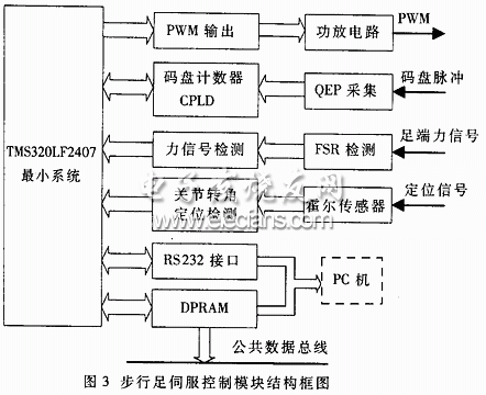
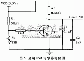
2 The hardware design of the single walking foot control system follows the above design scheme, adopts the bottom-up design idea to develop the robot crab control system to ensure the reliability of the system development, and also meets the modular design idea: after the overall determination Design the functional modules and combine them into a complete system by designing the interfaces between the modules. Firstly, the walking foot servo controller module is developed by using TMS320LF2407, which is synchronously carried out in order to cooperate with the development of the machine crab prototype body, which is beneficial to the compatibility between the control system and the controlled object. The walking foot servo module includes the DSP minimum system, RS232 communication interface, DPRAM interface, PWM output, motor code disc QEP signal detection, code wheel count, joint rotation initial positioning, force signal detection, etc., as shown in Figure 3. The functions of each peripheral interface of the servo control module are as follows: (1) RS232 communication interface: realize upper and lower communication between PC and LF2407, so as to control and state observation in single walking foot control experiment; (2) DPRAM interface: used for The actual controller crab control system multi-control module cascade communication and servo module communication with TMS320VC5410 system; (3) PWM output interface: use the TMS320LF2407 on-chip peripheral to generate digital PWM signal as motor control signal; (4) code wheel count Interface: used for quadrature coded signal (QEP) detection in motor speed detection, motor rotation direction judgment, combined with joint rotation angle positioning signal to detect joint rotation angle; (5) joint rotation angle initial positioning interface: acquisition for joint initial Positioned Hall sensor signal; (6) Force signal interface: handles and detects the contact force signal of the foot FSR sensor. Figure 4 Counter structure block diagram 2.1 TMS320LF2407 function introduction TMS320C24x series DSP chip is a low-cost and high-performance 16-bit fixed-point DSP introduced by TI in 1997. It is a DSP designed for digital motor control system and other control applications. . The TMS320C24x family of DSPs not only has a high-performance CPU core, but also features peripheral functions controlled by a single chip. It combines the high-speed computing power of a digital signal processor with the powerful control capabilities of a motor, making it an ideal replacement for traditional multi-microprocessor unit MCUs and multi-chip design systems. After comparing the functions of the TMS320C24x series chips, the TMS320LF2407 was selected as the CPU for developing the robotic walking foot control system. In addition to the high-speed and high-performance of the general-purpose DSP, the chip is also equipped with a large number of peripheral interfaces, dedicated to motor control development.
2.2 Design of the counter In the design process of the counter, the modular design idea is adopted. The adjustable parameterized component library (LPM-Library of Parameterized Modules) provided by MAX+plus II software is used to design the adjustable parameterized counter component LPM-counter. 16-bit counter. There are 9 parallel counting channels on the counter module. Each channel includes a 16-bit bidirectional reversible counter with preset initial value. The counting pulse is triggered by rising edge and has the functions of synchronous loading initial value and asynchronous clearing. . The block diagram of the counter is shown in Figure 4. In the module, a 4× frequency processing and direction judging function circuit of the motor QEP signal group is also included, and a logic circuit that interfaces with the DSP chip TMS320LF2407 is provided.

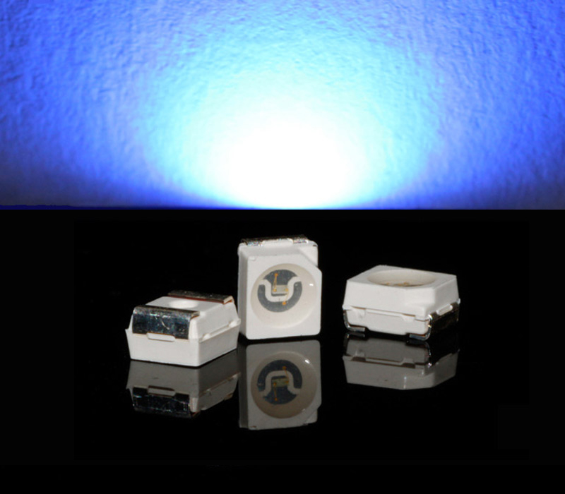
We are Blue SMD LED manufacturer from China.
Those Blue SMD LED was born for excellent lighting effects.
Need some really bright LEDs? Contact us now!

Blue SMD LED is easy to use in decorated your home or garden. It is also widely used in LED street lamps, LED traffic lights, LED backlight, Disney toys, LED color lighting products, LED lighting engineering and other fields as well.
In 18 years, we supply the Blue SMD LED with high efficiency, high luminance, low light attenuation has been recognized by our customers.
1, Blue SMD LED has a lots of size like: 2835 Blue SMD LED, 3020 Blue SMD LED, 3528 Blue SMD LED, 3014 Blue SMD LED, 3030 Blue SMD LED, 3535 Blue SMD LED, 5730 Blue SMD LED, 5050 Blue SMD LED and so on.
2, Variety of color available: deep blue SMD LED, Violet blue SMD LED, blue SMD LED, blue grow light SMD LED, sky blue SMD LED, light blue SMD LED, aqua blue SMD LED. For instance: 440nm purple-blue SMD LED, 445nm blue SMD LED, 450nm deep blue LED, 455nm Grow light blue SMD LED, 460nm Blue smd led, 465nm blue smd led, 470nm pale blue SMD LED, 475nm water blue SMD LED, 480nm Sky Blue SMD LED.
3, Different brightness: common brightness blue SMD LED, High light blue SMD LED, Super bright Blue SMD LED, Ultra bright Blue SMD LED.
4, Variety of power available: We can supply Blue SMD LED with 0.06W Blue LED, 0.1W Blue LED, 0.2W Blue LED, 0.5W Blue LED, 1W Blue LED, 3W Blue LED. We can also customized single chip Blue LED, double chips Blue LED, three chips Blue LED or multi chip Blue LED for you.
We will do the High temperature resistance testing and 10 hours ageing treatment before the product out off the factory, which can ensure the stability of each product. Our LED products have 5 year warranty. Please believe that we are the best supplier for your light-emitting diode.
Blue SMD LED
Blue SMD LED,Blue LED SMD,Super Bright SMD LED,Blue 2835 SMD LED
Shenzhen Best LED Opto-electronic Co.,Ltd , https://www.bestsmd.com
