
Mobile Robot Sensing System Circuit Design - Circuit Diagram Reading Every Day (236)
Ultrasonic sensors are one of the commonly used sensors for obstacle avoidance and ranging in mobile robots. When the sensor is mounted on the robot, it should not be too close to the ground. It is too close to cause interference signals, and it is easy to treat obstacles that can be overcome as insurmountable obstacles. The distance between the two probes of the sensor should not be too far or too close, too far measurement error is too large, too close crosstalk signal is too strong.
The robot hardware system mainly includes: ARM processor, single chip microcomputer, peripheral interface circuit, robot chassis and power supply, among which ARM processor is the core of the upper layer, and 51 single chip microcomputer is the core of the lower layer. The hardware structure block diagram is shown as in Fig. 1.
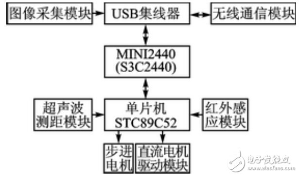
Figure 1 hardware block diagram
The mobile robot adopts the H-bridge control scheme, and the overall control scheme is shown in Figure 2.
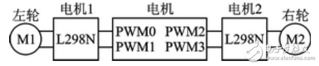
Figure 2 H-bridge control scheme
The motor has 4 PWM outputs for driving the left and right wheels respectively, and 2 motors can control one motor, and the two motors are connected in parallel.
When the L298N chip enable signal ENABLE is high, the output changes with the input, otherwise it is high impedance state, so when soldering, the ENABLE pin and the power pin VS are connected to the power supply VCC.
The specific driving process is as follows: the control chip sends a driving signal through the PWM through the programming, and the PWM output is used as the input of L298N, and the motor is rotated by the L298N conversion output control signal, thereby realizing the driving of the motor.
The PWM output signal can control the Dc Motor speed. When the duty ratio is increased, the speed increases; when the duty ratio decreases, the speed decreases; when the PWM signal output duty ratio is 0, the motor can be stopped.
When the left wheel stops and the right wheel rotates, the car turns left; when the right wheel stops and the left wheel turns, the car turns right. The positive and negative sequence conversion of the 2-way PWM output controls the forward and reverse rotation of the motor, which in turn controls the forward and reverse of the car.
The system software structure is shown in Figure 3.
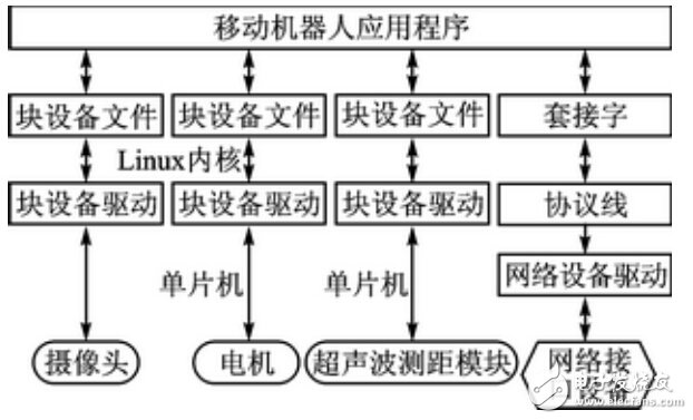
Figure 3 system software structure
Ultrasonic transmitter module design
When the applied signal frequency is equal to the natural vibration frequency of the two piezoelectric wafers, resonance will occur. The center frequency of the ultrasonic sensor used in the subject is 40 kHz. Therefore, in the ultrasonic transmitting circuit, the I/O port is set high by software programming. And set low, generate a 40kHz pulse signal, and output to the transmitting circuit. Because the AT89S51 microcontroller I / O port can provide 20mA sinking current, and the current sinking capacity is small, so 74HC04 to improve its output current, to ensure that the 40kHz pulse signal has a certain power. The schematic diagram of the ultrasonic transmitting module is shown in Figure 4.
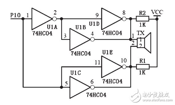
Figure 4 Schematic diagram of the ultrasonic transmitting module
Ultrasonic receiver module design
As shown in FIG. 5, the ultrasonic receiving processing circuit uses the integrated circuit CX20106. When the CX20106 receives a signal corresponding to its center frequency, the 7 pin outputs a low level. The pulse falling edge of the 7-pin output and the infrared sensor ranging signal are connected to the MCU interrupt port.
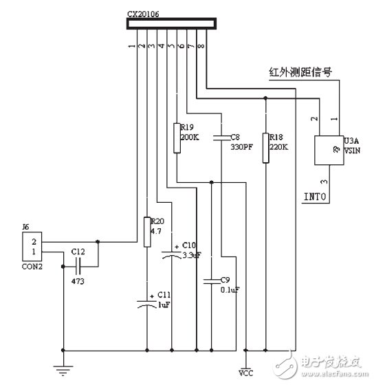
Figure 5 Schematic diagram of the ultrasonic receiving circuit
Reflective infrared sensor detection system design
The infrared ranging circuit is shown in Figure 6. The LM567 can form a low-frequency oscillator as the encoding circuit of the infrared sensing system, that is, using its internal voltage-controlled oscillator to generate low-frequency signals, since R25=10.9kΩ, C25=2200pF, according to The formula f0 =1/1.1RC, the 5-pin output signal with a frequency of 38.91 kHz. This pulse signal causes transistor T1 (8050) to operate in a switching state, driving an infrared pulse from the infrared light emitting diode. The use of this method eliminates the signal generation circuit, simplifies the line and debugging work, and prevents the difference between the surrounding environment and the component parameter variation on the transmission and reception frequency, realizes the synchronous automatic tracking of the infrared transmission and reception working frequency, and makes the circuit The stability and anti-interference ability are greatly enhanced.
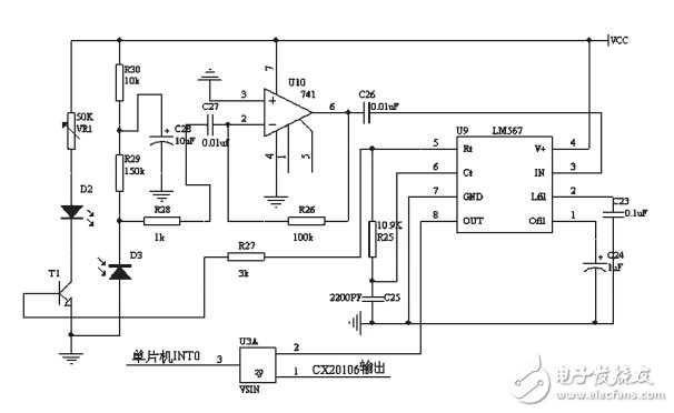
Figure 6 Reflective infrared sensor ranging schematic
Edit Comment : The article uses the advantages of ultrasonic sensor and infrared sensor to design a mobile robot sensing system based on ultrasonic sensor and infrared sensor. The system uses infrared sensors to compensate the detection dead zone of the ultrasonic sensor, so that the mobile robot has a larger sensing range.
Electronic enthusiasts "Wireless Communications Special Edition", more quality content, download now

Coreless Motor product introduction:
Coreless Motor, small size, light weight (cylinder) - radial rotation/weeks to rotation (flat) - low noise, low power consumption, strong sense of vibration - simple structure - reliability - response time short Micro Vibration Motor is mainly used in mobile phones, toys, adult health supplies, etc

Function: fast speed, suitable for aircraft model, electric toothbrush,USB fan and other products.

Characteristic: the volume is 6MM 7MM fast.
Features: small size, fast speed, dc high speed motor starting voltage 0.6v is not possible for other motors.Wear shaking head, strong vibration feeling.

Operating temperature range:
Coreless Motor should be used at a temperature of -10~60℃.
The figures stated in the catalog specifications are based on use at ordinary room temperature catalog specifications re based on use at ordinary room temperature (approximately20~25℃.
If a Coreless Motor is used outside the prescribed temperature range,the grease on the gearhead area will become unable to function normally and the motor will become unable to start.Depending on the temperature conditions ,it may be possible to deal with them by changing the grease of the motor's parts.Please feel free to consult with us about this.
Storage temperature range:
Coreless Motor should be stored ta a temperature of -15~65℃.
In case of storage outside this range,the grease on the gearhead area will become unable to function normally and the motor will become unable to start.
Service life:
The longevity of Coreless Motor is greatly affected by the load conditions , the mode of operation,the environment of use ,etc.Therefore,it is necessary to check the conditions under which the product will actually be used .The following conditions will have a negative effect on longevity.Please consult with us should any of them apply.â—Use with a load that exceeds the rated torque
â—Frequent starting
â—Momentary reversals of turning direction
â—Impact loads
â—Long-term continuous operation
â—Forced turning using the output shaft
â—Use in which the permitted overhang load or the permitted thrust load is exceeded
â—A pulse drive ,e.g.,a short break,counter electromotive force,PWM control
â—Use of a voltage that is nonstandard as regards the rated voltage
â—Use outside the prescribed temperature or relative-humidity range,or in a special environment.
â—Please consult with us about these or any other conditions of use that may apply,so that we can be sure that you select the most appropriate model.
when it come to volume production,we're a major player as well .each month,we rurn out 600000 units,all of which are compliant with the rohs directive.Have any questions or special needed, please contact us, we have the engineer group and best sales department to service to you Looking forward to your inquiry. Welcome to our factory.

Coreless Motor
Coreless Motor,Micro Coreless Motor,7Mm Coreless Motor,Micro 6Mm Coreless Motor
Shenzhen Shunchang Motor Co., LTD. , https://www.scgearmotor.com