
New hybrid vehicle detection technology
As a new development direction of the automotive industry, Hybrid Electric Vehicle (HEV) has received the attention of the state. Hybrid vehicle technology avoids the shortage of pure electric vehicles in battery technology and energy infrastructure, and has become a hot spot in the research and development of new vehicles in the near future. After the support and development of the National "863 Program", China's hybrid vehicle technology is rapidly moving towards industrialization.
This article refers to the address: http://
1 Hybrid control system
There are three key factors in the realization of a hybrid vehicle: a system that can monitor the running status of the vehicle in detail; analyze the information acquired by the monitoring system and issue corresponding control commands; the electronic control system of the hybrid vehicle works in the vehicle compared to the general electronic system. In a very harsh environment, electromagnetic interference, vibration, dust, etc. will cause technical bottlenecks, as shown in Figure 1.

In this paper, the hybrid vehicle is studied, the core technology of each important component of the hybrid vehicle is systematically analyzed, and an economical and practical design example of the control system of the hybrid vehicle is proposed. The system adopts advanced computer technology and bus technology, integrates intelligent control, signal acquisition, data processing and communication, and has good real-time control. It realizes intelligent control of the whole vehicle and effective integration between multiple sensors.
2 power control strategy system
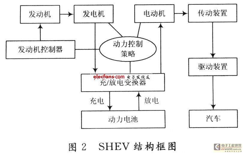
Hybrid electric vehicles are powered by engines and batteries. Engines and motors can be combined in different ways to achieve different drive options, such as series, parallel and hybrid. The performance of the vehicle is not only related to components such as the engine and the motor, but also related to its control strategy and optimization method. Hybrid electric vehicles can be divided into series hybrid electric vehicles (SHEV) and parallel hybrid electric vehicles (PHEV) according to the power combination. The research object in this paper is SHEV. The characteristics of SHEV are suitable for frequent starting, acceleration and low-speed operation conditions in urban driving, which can make the engine run stably around the best working point. By adjusting the output of the battery and the motor to achieve the purpose of adjusting the speed, thus improving the complex working conditions. The fuel economy of the vehicle under driving while reducing emissions. When the state of charge (SOC) of the battery is high, the engine can be turned off, and only the motor is used for power output, so that the engine can be prevented from operating under idle speed and low speed conditions, improving engine efficiency and reducing harmful substances. The structure of SHEV is shown in Figure 2.
Hybrid vehicles need to determine their corresponding control strategies based on different driving conditions and real-time parameters of the power battery. The "Power Control Strategy System" analyzes and processes the data from the health monitoring system to determine whether the motor should be in the engine operating mode, the power battery operating mode, or the cooperative operating mode, and then issue corresponding control commands. Studies have shown that a good system control strategy should be to operate the engine at 50% to 65% of its maximum load, while also taking into account the power of the car. An important basis for strategy control is the SOC value of the power battery. When the SOC value is in the normal working area (30% to 75%), the power battery discharge current is in the range of 20 to 65 A. If the driver accelerates the vehicle at this time. Below 30%, a power battery can be used to drive the vehicle. When the driver's request for acceleration is 30% to 65%, the excess energy released by the engine at this time can be used to charge the power battery. When the driver's request for acceleration is 65% to 80%, the car is independently driven by the engine until its maximum output power. When the acceleration requirement is greater than 80%, the vehicle can be driven simultaneously by the engine and the power battery.
In addition, it is necessary to consider the safety and life of the power battery. When the SOC value changes beyond the above range, it is necessary to issue corresponding control commands in a timely and reasonable manner. When the SOC is greater than 80%, the power battery is forced to discharge, and the control system needs to change the proportion of the power mixture at this time, and increase the ratio of the power battery to the total output power. At this time, the rich energy generated by the engine is not recovered. When the SOC is less than 20%, the power battery enters the forced charging mode, at which time a part of the output power of the engine is used for charging the power battery, and the vehicle is completely driven by the engine at this time.

3 signal channel
The processor system processes the collected signals and sends them to the upper power strategy control system, and the upper control signals are also transmitted to the bottom layer. This system uses two CAN transceivers to accomplish this task. Adopting CAN bus technology, it is not only free networking, strong scalability, good real-time performance, high reliability, but also has self-diagnosis and monitoring capabilities. It is a very effective communication method. The CAN bus has the following features:
(1) Bus arbitration based on priority competition without damage;
(2) can be transmitted by means of receiving filtered multi-address frames;
(3) It has error detection and error frame automatic resend function;
(4) Data transmission methods can be classified into data broadcast type and remote data request type.
In addition, the system also has a RS 232 transceiver, mainly used for debugging during the design process and quality inspection during the production process. Battery voltage and temperature measurement
The measurement method of the power battery voltage depends on the specific conditions of the power battery. The system uses nickel-metal hydride batteries, which can be divided into 12 groups of batteries. Each group of batteries includes 10 small batteries, each battery has a voltage of 1.2 V, so each group of voltages is 12 V, total voltage is 144 V. In order to ensure that the measuring system is suitable for different working conditions, especially considering that the battery voltage will rise properly during charging, the voltage may reach 20 V in special cases, so the designed measuring range should be 0-20V.
The temperature is measured by the digital temperature sensor DS1860. This sensor can use multiple sensors, a total of one data line and one power line and one ground line. It has the advantages of simple operation and less input port.
Charge and discharge current measurement
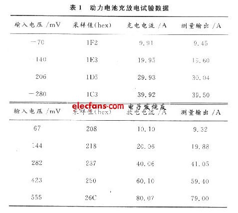
The high current of the power battery can be measured and charged in two ways. The most common one is the Hall sensor. Therefore, choosing the right Hall sensor is the key to accurate measurement circuits. The magnetic field sensitivity of the Hall sensor or the starting point of the magnetic field is matched to the motor type and structure. Different motor types and different motor design structures The rotor magnetic field has different magnetic field distributions and magnetic field fluctuations. If the magnetic sensitivity of the Hall sensor is too high or too low, the position sensor will give an erroneous signal due to the irregular fluctuation of the magnetic field distribution of the rotor magnet and the magnetic steel. In addition, consider the antistatic capability of the Hall sensor chip, the surge voltage or surge current capability of the Hall sensor chip. The system studied in this paper uses a Hall sensor of the type UGN3503UA. In the design of the measurement circuit, it should be noted that the output of the sensor is milliampere current, so it is necessary to select a suitable input resistor to convert it into a voltage signal, and use a higher precision amplification and sampling circuit. Table 1 shows the results of one experiment of the system.
The increase in fuel costs and the increase in people's awareness of environmental protection make hybrids no longer synonymous with high costs. At present, there is no hybrid vehicle with independent property rights in China, so the research on hybrid vehicles not only provides some experience for domestic counterparts.
N-NET Repeaters (single-/multi-mode converters) are applied in 100Mbps fast Ethernet /1000Mbps Gigabit Ethernet Network which is wired with both single mode fibers and multi-mode fibers. It can not only fulfill the conversion of single mode and multi-mode at 1310nm wavelength, but also that of 850nm/1310nm and 1550nm wavelengths, which functions as a relay and then makes multi-mode fibers transmit farther. It supports transmission in multi-mode dual fiber, single mode dual fiber and single mode single fiber.
Signal Booster Repeater,Wireless Repeater,Dual Band Signal Repeater,Mobile Repeater,3R Repeater, 10G 3R Converter Repeater
Shenzhen N-net Technology Co.,Ltd , http://www.nnetswitch.com