
Remote control in the living room - homemade USB computer remote control
I bought an LCD TV at home, and I was equipped with a laptop next to it. It was really comfortable to sweep the dishes in the sofa, especially in such a winter, but I often changed the dishes, fast forward, and adjust the volume. It was really uncomfortable. Especially when I was forced to operate the computer by my wife, I really couldn’t wait a few meters.
This article refers to the address: http://
It seems that the lazy people need to advance the scientific and technological progress, and the idea of ​​using a remote control to control the computer. Everyone has it. When the Internet is scared, it seems that there are many smart lazy people, and there is a feeling of finding an organization. First look at their research results, one is to use the serial port, but now many computers have canceled this interface, my notebook is estimated to be no play. The other is my favorite USB interface, but I need a microcontroller, but also program download, dizzy.
After several months of research, finally, I finally found a way to use a USB interface without a single-chip microcomputer. I dare not hide it, and I shared it with the lazy people I encountered, so that everyone can operate the computer in the living room. It is. However, if the operation is too complicated, it is recommended to use the wireless mouse and keyboard, because the remote control alone estimates that some friends will be crazy.
First, the principle articles
Like a wireless mouse, controlling the computer with a remote control also requires a receiver (see Figure 1). This receiver receives infrared signals from various remote controls, then forwards them to the computer, receives them from the computer, decodes them, and finally passes the software. Control the player and operating system. The remote control can be selected at will, with either an idle or an old remote control (see Figure 1 below), as long as it is not an air conditioner remote. Everyone wants to use the functions of pause, fast forward, next episode, volume adjustment, CD-ROM drive, computer shutdown, etc.; advanced functions include analog mouse, typing, etc.; advanced functions include remote start, 200 meters remote control.
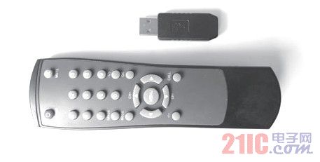
figure 1
So the key is to do the receiver and software.
Second, hardware articles
The receiver is finished as shown in Figure 2.
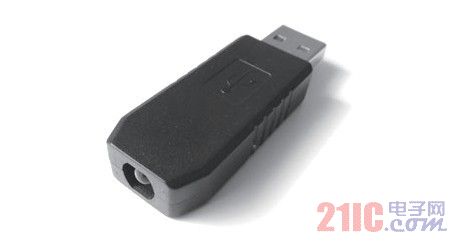
Figure 2 Receiver finished product
Component table (physical object shown in Figure 3).
Component table
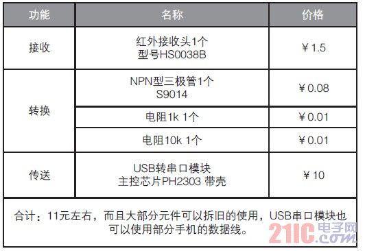

Figure 3 physical map
The receiver circuit diagram is shown in Figure 4.
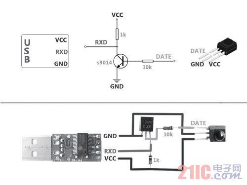
Figure 4 receiver circuit diagram
The internal diagram of the receiver is shown in Figure 5.
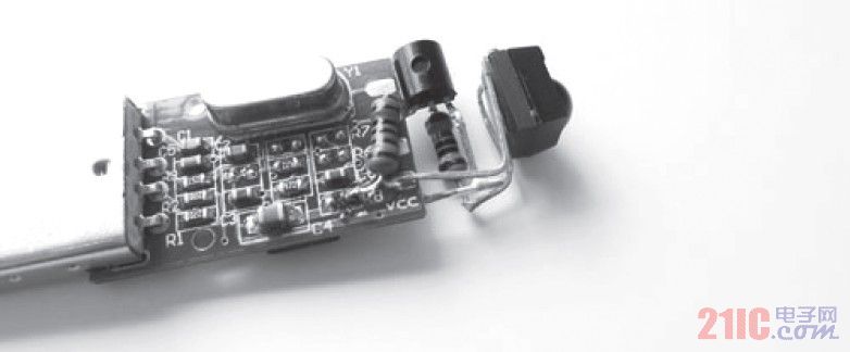
Figure 5 receiver internal diagram
Analyze the various components in the diagram.
1. The USB to serial port module is located on the left side of Figure 5. The appearance before soldering is shown in Figure 6.
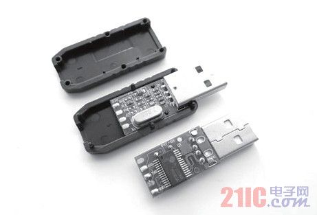

Figure 6
This module is a signal that can convert serial signals to USB. It is compact and stable. It is responsible for passing the signal received by the infrared head to the computer.
2. Infrared head Figure 5 The infrared integrated receiver on the right side is a device that combines receiving, modulating, and transmitting. The signal coming out is directly pulsed, which can be easily connected to a single-chip microcomputer or other equipment. But since the pulse it outputs is exactly opposite to the pulse of the USB to serial port module, we need to add an inverter circuit.
3. Level-shifting circuit Figure 4 The circuit consisting of three components in the middle, a familiar friend must know that it is an inverter, also called "non-gate". In addition, it also functions as a level shifter.
4. Pay attention to the welding: you need to touch the infrared head with your hand every time you test it. It may cause heat in the infrared hair due to circuit problems. At this time, you need to re-examine the circuit to avoid burning the board and the infrared head.
Third, the software articles
1. Install the driver for the receiver: USB to serial port module requires driver. You can download the latest driver from the official website of PL2303. Website: http://?ID= 31.
Insert the created receiver and the system recognizes that the installation was successful. Go to the System Manager of the system and look at the ports that are virtualized by this module. As shown in Figure 7.

Figure 7
2. Install control software for the computer: Recommend the domestic IRCtrl 2.4.1, the setting of this software is relatively simple, in line with everyone's habits, the specific will not explain, pay attention to two points:
(1) Select the correct port number as shown in Figure 8.

Figure 8
(2) Use the Learn Infrared Code button (the learning button is only a test, pay attention to save the infrared information) as shown in Figure 9.

Figure 9
Fourth, the effect of articles
Seeing the picture of the title, some friends may ask, the receiver is inserted on the side of the notebook like a USB flash drive, and the remote control is not aligned with the infrared receiver.
In fact, it doesn't matter much. If it is not aligned, the white wall can also help you to reflect. If you are not satisfied, you can use the USB extension cable to adjust. The actual test supports almost all remote control models in the home. The test distance is 4.5 meters. It is tested successfully on two computers. It supports regular functions and advanced functions. More functions are expected to be perfected with everyone.
Coupletech Co., Ltd. is a manufacturer of professional Q-switches and Modulators. We have integrated fabrication technologies, endless perfection, unending innovation for product quality. Besides, we also offer special need For custom design. Here you will find information on a wide range of electro optic and passive optical components such as Pockels cells, Q-switches, electro-optic phase and amplitude modulators.
Coupletech could supply a variety of different types of longitudinal and transverse Pockels cells for Q-switching, modulation, pulse picking. e.g. BBO Q-Switch ( BBO Pockels Cell ), DKDP Q-Switch ( DKDP Pockels cell ), LN Q-Switch ( LN Pockels cell ), RTP Q-Switch ( RTP Pockels cell ), KTP Q-Switch (KTP Pockels cell). and so on.
Pockels Cell
Electro-optic Components, BBO Pockels Cells, LN Pockels Cells, KTP Pockels Cells, DKDP Pockels Cells, EO Q-Switches, LGS Pockels Cells, RTP Pockels Cells
Coupletech Co., Ltd. , https://www.coupletech.com