
A text to bring you a deep interpretation of the angle sensor
Angle Sensor Definition
An angle sensor is a device that detects angular position and converts it into an output signal. As the name implies, these sensors are used to measure angles. They typically have a hole in the body designed to fit a LEGO axle. When connected to an RCX (a programmable brick used in LEGO Mindstorms), the angle sensor counts once every 1/16th of a full rotation. The count increases when rotating in one direction and decreases when the direction changes. The initial position of the sensor affects the count value, which is usually set to zero during initialization. This can be reset through programming if needed.
By calculating the angle of rotation, both position and speed can be easily determined. For example, when a wheel is attached to a robot or a gear is used for movement, the distance traveled can be calculated using the angle of rotation and the wheel's circumference. From this, you can derive speed by dividing the distance by time.
The basic equation for calculating distance is: Distance = Speed × Time
This leads to the formula: Speed = Distance / Time
Magnetic Sensitivity Angle Sensor
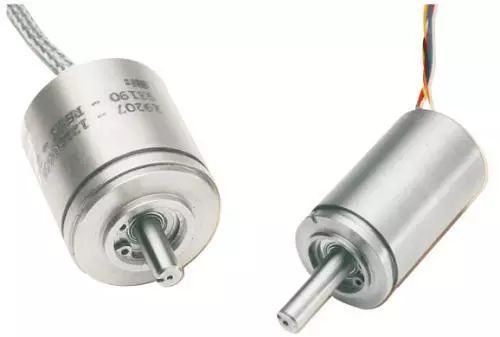
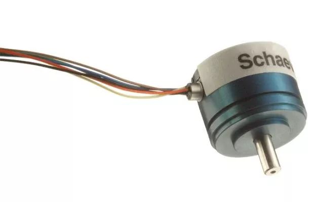
A magnetic sensitive angle sensor uses a high-performance integrated magnetic sensor to detect non-contact angles. It works with a microprocessor to process signals and create a new generation of angle sensors. These devices are ideal for applications where contact-based sensors might fail due to wear or environmental factors.
Features: Non-contact operation, high sensitivity, near-infinite rotation life, no noise, high repeatability, and excellent frequency response.
Advantages:
1. Automatic compensation for misalignment of the magnet.
2. Fault detection capability.
3. Non-contact position detection, suitable for harsh environments.
Applications:
1. Measuring rotational speed and angle in industrial machinery, construction equipment, and aerospace systems.
2. Car electronics, such as throttle position, steering wheel angle, seat position, and headlight alignment.
3. Robotics, motion control, and motor rotation monitoring.
Pull-Wire Displacement Sensor Based on Magnetic Sensitivity Technology
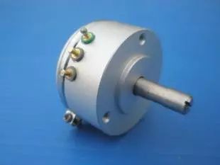
Conventional pull-wire displacement sensors use potentiometers to convert mechanical movement into resistance or voltage output. However, these sensors suffer from issues like wear, limited resolution, and poor high-frequency performance. In contrast, pull-wire displacement sensors based on magnetic sensitivity technology use a magnetic field to transmit displacement information, offering improved accuracy and durability.
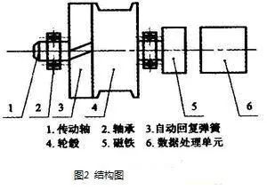
These sensors replace mechanical displacement with an electrical signal that can be measured, recorded, or transmitted. They consist of a spring, hub, magnet, and data processing unit. The magnetic field rotates as the wire moves, and the sensor captures this change to calculate displacement.
Unlike traditional contact sensors, these models eliminate physical wear and improve system stability. The microprocessor processes the magnetic field angle, converting it into displacement data. The communication interface allows the sensor to interact with external systems, ensuring accurate and reliable measurements.
Function of Each Component:
1. The wire is wound around a hub connected to a magnet. As the wire moves, the hub rotates, changing the magnetic field angle.
2. The magnetic sensitive angle sensor and magnet are aligned on the same axis. The microprocessor reads the magnetic field angle and calculates the displacement.
3. The communication interface enables the sensor to receive commands and send back displacement data.
Hardware Interface Circuit
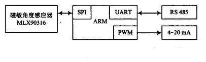
The data processing unit includes a magnetic sensitivity angle sensor, a microprocessor, a communication interface, and an output module. The microprocessor processes the received magnetic field data and converts it into displacement information using a mathematical model based on the hub’s diameter.
Capacitive Angular Displacement Sensor
Capacitive angular displacement sensors measure the angle between a fixed and a rotating component. They are widely used in industry due to their high accuracy, sensitivity, and suitability for dynamic measurements. However, they require precise manufacturing and installation to avoid errors caused by temperature or material changes.
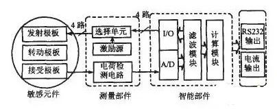
These sensors often use a differential structure to overcome limitations, improving accuracy and reliability. The system includes sensitive components, measuring circuits, intelligent processing units, and interface components that convert capacitance values into angular displacement readings.
Block diagram of the sensor system is shown above.
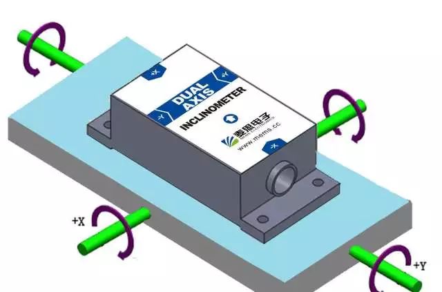
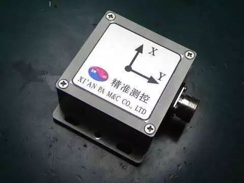
Tilt Sensor
Tilt sensors are commonly used to measure horizontal orientation. They come in three types: solid pendulum, liquid pendulum, and gas pendulum. These sensors can also measure inclination relative to the horizontal plane.
Basic Principle of Tilt Sensors
Based on Newton’s second law, tilt sensors measure acceleration rather than velocity. If the initial velocity is known, the linear velocity and displacement can be calculated. This makes them essentially acceleration sensors that rely on inertia.
When stationary, the sensor only experiences gravitational acceleration. The angle between the gravity vector and the sensor’s axis indicates the tilt angle.
With the advancement of MEMS technology, inertial sensors like micro-accelerometers have become highly integrated, allowing for compact, reliable tilt sensors. These devices integrate microcontrollers, accelerometers, ADCs, and communication modules, making them easy to use and highly accurate.
Classification of Tilt Sensors
"Solid Pendulum" Inertial Device
Uses a force-balanced servo system with a pendulum, cycloid, and bracket. Strain-type tilt sensors operate on this principle.
"Liquid Pendulum" Inertial Device
Uses conductive liquid in a glass casing with electrodes. When tilted, the resistance between electrodes changes, reflecting the angle of inclination.
Some designs use bubbles in the liquid to detect changes in capacitance when the device tilts.
"Gas Pendulum" Inertial Device
Heated gas creates convection currents that behave similarly to a pendulum. The resistance of a hot wire inside a sealed cavity changes with tilt, providing a way to measure the angle.
Comparison of Solid, Liquid, and Gas Pendulum Performance
Each type has its advantages. Gas pendulums are lightweight and resistant to vibration but less accurate. Solid pendulums are precise and widely used in weapon systems. Liquid pendulums offer high stability and are common in high-precision applications.
Other Angle Sensors
RFA4000 Series
Non-contact, wear-free, and capable of 360° measurement. Features include IP67 protection, 12-bit resolution, and high cost-performance. Ideal for space-constrained installations.
CK Series
Uses intelligent magnetic sensors for non-contact angle measurement. Suitable for harsh environments and offers multiple output formats, including analog, PWM, and SPI. Can be equipped with display instruments for alarm, setting, and communication functions.
Selection Criteria for Angle Sensors
1. Frequency Response Characteristics
The sensor’s frequency response determines the range of measurable frequencies. A higher frequency response allows for more accurate dynamic measurements.
2. Sensitivity
Higher sensitivity improves signal strength but may increase noise. Choose a sensor with a good signal-to-noise ratio for accurate results.
3. Stability
Stability refers to the sensor’s ability to maintain accuracy over time. Environmental conditions significantly impact long-term performance, so choose a sensor with strong environmental adaptability.
4. Linear Range
The linear range is where the sensor’s output is proportional to the input. A wider range ensures greater accuracy and flexibility in measurement.
In conclusion, selecting the right angle sensor depends on specific application requirements, including accuracy, environment, and budget. No single factor determines quality—each sensor must be evaluated based on its suitability for the intended use.
High-frequency Transformer,Switching Power Supply Transformer,Ring Electronic Transformer,High Frequency Electrical Transformer
Xuzhou Jiuli Electronics Co., Ltd , https://www.xzjiulielectronic.com