
ARM embedded development board automotive energy-saving control system
introduction
For a variety of reasons, buses are constantly repeating the process of accelerating—decelerating or stopping—and accelerating. By installing the energy-saving device, when the car needs to be braked, under the control of the main control unit, the huge kinetic energy of the vehicle can be converted into the potential energy of the high-pressure gas through the air compressor and stored, thereby realizing the vehicle deceleration or parking. When the car needs to be started or accelerated, the stored high-pressure gas potential energy is used instead of the fuel to drive the car, thereby realizing the recycling of the vehicle energy and achieving the energy-saving effect. At the same time, since the car consumes the most energy when starting or accelerating, if the car is driven by fuel, the fuel is not fully burned at this time, the combustion effect is the worst, and the noise generated is the largest.
How the system works
The system is mainly composed of three parts, namely the detection part, the control part and the actuator. The detection portion includes detection of signals such as a pedal position sensor, a crank position sensor, a compressor piston position sensor, a vehicle running speed sensor, a gas tank pressure sensor, and the like. Actuators mainly include two-way controllable solenoid valves and electromagnetic clutches. The control part is mainly composed of a control system composed of an ARM microprocessor and some peripheral circuits. This article mainly introduces the control part of the system. The function of the device is to change the kinetic energy of the car that should be consumed by friction during braking to be consumed by the potential energy of the gas. At the time of starting, the high-pressure gas potential energy stored in the gas storage tank is used to drive the car to walk when the brake is used. When the vehicle speed reaches a certain value, such as 20km/h, it is switched to the mode driven by the car engine.
System hardware design
Because the energy-saving device needs to detect more simulations, such as the pressure inside the gas storage tank, the position of the brake pedal, the speed of the vehicle, the running position of the piston and the position of the accelerator pedal, and some of them need to be monitored in real time, such as a gas storage tank. The internal pressure, etc., can be achieved by using a multi-tasking executive, and ordinary single-chip microcomputers cannot meet this requirement. Therefore, according to the actual situation, choose the appropriate processor chip, plus various data and program memory chips to form the minimum system. At the same time, the data acquisition, display, communication interface, control execution unit and power management module are added to form a complete control system. Due to the wide range of CAN fieldbus applications for automotive applications, the CAN bus interface has been added to facilitate the connection with the control system of the vehicle, thereby constituting the entire hardware system. The overall block diagram of the system is shown in Figure 1.
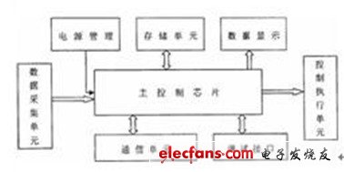
Figure 1 system block diagram
S3C44BOX
Because the design requires the system to collect signals and monitor in real time, the requirements of the main control module are high. Therefore, the main control module should be a minimum system composed of a high-performance microprocessor. According to the requirements of specific applications and the actual application, Samsung's ARM chip S3C44BOX was selected. The main performances are as follows:
Samsung's 16/32-bit RISC processor S3C44BOX provides a cost-effective and high-performance microcontroller solution for general-purpose applications. In order to reduce costs, S3C44BOX provides a wealth of built-in components, including: 8KB Cache, internal SRAM, LCD controller, 2-channel DART with automatic handshake, 4-channel DMA, system manager (chip select logic, FP/EDO/SDRAM Controller), 5-channel timer with PWM function, I/O port, RTC, 8-channel 10-bit ADC, IIC-BUS interface, IIS-BUS interface, synchronous SIO interface and PLL multiplier.
The outstanding feature of the S3C44BOX is its CPU core, which is a 16/32-bit ARM7TDMI RISC processor (66MHz) designed by ARM. The ARM7TDMI architecture features an integrated Thumb compressor, ICE (In Circuit Emulator) breakpoint debugging support, and a 32-bit hardware multiplier.
Data acquisition unit
The function of the data acquisition unit is to collect and process the required analog signals and send them to the processor for processing. In this unit, the core is the conditioning of the analog signal. Since the system collects data such as pressure data in the air tank of the car, position data of the brake pedal, vehicle speed, clutch engagement position, and accelerator pedal position, multiple data acquisition channels are required. The data of each channel must be processed before being sent to the processor for processing. The signal acquisition channel block diagram of the acquisition unit is shown in Figure 2.
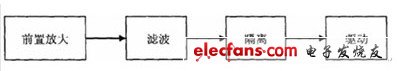
Figure 2 signal acquisition channel
Control execution unit
The function of the control execution unit is mainly to receive the digital quantity sent by the processor, and after being isolated and driven, it is sent to an actuator such as a solenoid valve, a relay, a clutch, etc. to perform corresponding actions. The functional block diagram is shown in Figure 3.
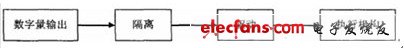
Figure 3 Control Execution Unit
This level is relatively simple, but in order to prevent external interference to the system, isolation must be used. The isolation device can be used with a common photoelectric trap, and the system uses TLP521-1.
Data display module
In the design of the system, in order to monitor the collected data, the debugging is more convenient and intuitive, so the data display module is added. The S3C44BOX integrates an LCD (Liquid Cristal Display) controller that supports monochrome, 4-level, 16-level grayscale, and 256-color displays on the LCD. It has strong versatility and functions as an LCD controller for the S3C44BOX. It is to transfer the data in the buffer to the external LCD driver and generate the necessary LCD control signals. The LCD controller can be programmed to support different horizontal and vertical points (640 & TImes; 480, 320 & TImes; 240, 160 & TImes; 160, etc.), different data line widths, different interface timing and refresh rate LCD, support 4-bit dual scan, 4-bit single scan 8-bit single scan mode with horizontal/vertical scrolling to support larger screen displays (eg 1280&TImes; 1280).
Since different sized LCDs have different numbers of vertical and horizontal pixels, data interfaces, data widths, interface times, and refresh rates, the LCD controller in the S3C44BOX can program the corresponding register values ​​to accommodate different LCD panels. The logic block diagram of the LCD controller is shown in Figure 4 below.
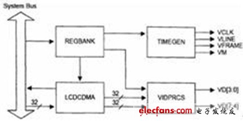
Figure 4 LCD controller logic block diagram
Power module
In this system design, a single 9V power supply from the external supply system, through the three-terminal regulator AS1117-5.0, AS1117-3.3 and AS1117-2.5, get 5.0V, 3.3V and 2.5V respectively. The AS1117 series regulators can supply up to 800mA. Because the system consumes less power and the maximum demand current does not exceed 300mA, the AS1117 is sufficient to meet the system's power requirements. The other two ±15V supplies are supplied by a DC/DC converter. Considering that there are digital circuits and analog circuits in the system, since the current of the digital circuit changes rapidly, it is easy to generate pulse interference, which affects the sampling accuracy of the analog signal, so the digital ground and the analog ground should be separated.
Power Plug Adapters,Output 12V 1A Power Adapter,12V 1A USB Power Adapter,12V 1A Electrical Power Adapters
Dongguan baiyou electronic co.,ltd , https://www.dgbaiyou.com