
Circuit breaker anti-jump circuit wiring principle - Database & Sql Blog Articles
1. The Role of the Anti-Jump Circuit
A1. Prevents the control switch or automatic device from failing to return in time—such as when an operator doesn’t release the handle or the closing contact gets stuck. This can lead to repeated closing of a faulty line or equipment, causing unnecessary tripping of the circuit breaker.
B1. A key function of the current-starting and voltage-holding electrical anti-jump circuit is to prevent damage caused by improper adjustment of the circuit breaker’s auxiliary contacts due to slow trip circuit displacement. This can result in the protection outlet contact being burned, which is particularly problematic for microcomputer protection systems and often overlooked.
2. Typical Wiring of the Anti-Jump Circuit
Common anti-jump circuits include series, parallel, spring energy storage, and trip coil auxiliary contact types. Most domestic circuit breakers use the series anti-jump circuit, which is considered the most reasonable and widely used. It not only prevents the circuit breaker from jumping but also protects the outlet contact from arc damage, making it essential for modern microcomputer protection devices.
The series anti-jump circuit is more reliable than others. While other types only prevent jumping, the series type also ensures that the outlet contact isn't damaged by arcing. However, some anti-jump circuits, like the trip coil auxiliary contact type, may risk burning the trip coil if left energized for too long.
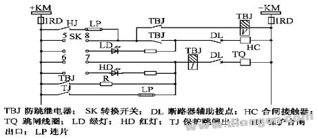
2.1 Series Anti-Jump Circuit
In a series anti-jump circuit, the anti-jump relay (TBJ) is triggered by current and connected in series with the trip circuit of the circuit breaker. The voltage-holding coil is connected in parallel with the closing coil. When a fault occurs, the relay protection activates, closing the protection outlet contact (TJ). This starts the TBJ's current coil, causing the circuit breaker to trip. The normally closed contact of TBJ then opens the closing circuit, while a pair of normally open contacts energizes the voltage coil, maintaining the trip state. If the SK (5-8) or HJ contact fails to return, the closing command cannot be executed, thus preventing the circuit breaker from re-closing. Additionally, the TBJ’s normally open contact provides self-protection, ensuring the outlet contact doesn’t arc until the circuit breaker fully opens. This setup is shown in Figure 1.
2.2 Parallel Anti-Jump Circuit
This type connects the anti-jump relay’s voltage coil in parallel with the circuit breaker’s closing circuit (as shown in Figure 2). For example, when a permanent closing command is issued, the output of the closing rectifier bridge turns on through Y3, S2, S3, S1, and KO (2-1). Once the circuit breaker closes, the auxiliary contact S3’ in the closing circuit closes, activating the anti-jump relay KO. The KO contact switches from 2-1 to 4-1, opening and holding the closing circuit. If a fault occurs at this point, the relay protection will trip the circuit breaker. Since the closing circuit is already disconnected, the circuit breaker cannot close again, effectively preventing it from jumping.

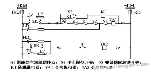
2.3 Spring Energy Storage Type Anti-Jump Circuit
As illustrated in Figure 3, when a permanent closing command is received, the closing current flows through SK or HJ, S3, K1, K1, S2, S1, and YA1. After the circuit breaker closes, the spring mechanism begins to store energy. The spring energy storage auxiliary switch S3, connected in parallel in the closing circuit, activates the anti-jump relay K1. Its normally open contact self-protects, while its normally closed contact opens. If a fault occurs, the relay protection trips, and since the closing circuit is already disconnected, the circuit breaker cannot jump again.
2.4 Trip Coil Auxiliary Contact Type Anti-Jump Circuit
As shown in Figure 4, when a short-circuit occurs during the closing process, the protection device triggers the circuit breaker to trip. The normally open auxiliary contact TQ 2, operated by the trip coil, closes, keeping the trip coil energized. Meanwhile, the normally closed contact TQ 1 opens, cutting off the closing circuit. If the closing command still exists, the circuit breaker won’t close again. Once the command is released, the trip coil loses power, and the system returns to its original state.
3. Issues to Be Aware of During Application
A1. For circuit breakers without built-in anti-jump devices, an electrical anti-jump circuit should be installed. The series anti-jump circuit is the most effective and should be prioritized for dual benefits.
B1. The starting current coil of the series anti-jump relay should be selected based on sensitivity of at least 2, and the polarity of the current and voltage coils must match during installation.
C1. If the protection device or switch mechanism already has an internal anti-jump circuit, it is recommended to use the one within the protection device and remove the one in the operation mechanism to ensure reliability and ease of maintenance.
D1. Some believe that the spring energy storage mechanism itself has anti-jump functionality, so an additional electrical anti-jump circuit might not be needed. However, the energy storage mechanism does not prevent the circuit breaker from jumping due to the closure of the closing contact or protect against arc damage to the outlet contact. Therefore, it is better to install an electrical anti-jump circuit for added safety.
Transform Solution,Transformer Test Lab,Transformer Bushing,Transformer Design Optimize
Hangzhou Qiantang River Electric Group Co., Ltd.(QRE) , https://www.qretransformer.com