Design and Implementation of a Low-cost Automobile Security System Based on MMS
Design and Implementation of a Low-cost Automobile Security System Based on MMS
1. Introduction With the continuous improvement of people's living standards, personal ownership of cars has become more and more common. However, the subsequent problem of frequent theft of vehicles has received increasing attention. The traditional automobile security system takes the global satellite positioning system (hereinafter referred to as GPS) as the core. The biggest advantage of this technology is that it can locate the stolen vehicle and control the vehicle remotely, but it cannot obtain image and sound information and cannot understand the vehicle. The environment of the place cannot effectively hunt down the suspect. There are also some systems that use GPRS to transmit image data in real time. This scheme is severely restricted by network bandwidth, has poor image quality, requires high computing power from the processor, and has high system usage costs. 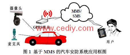
In response to the above problems, we proposed and designed a multimedia information service (MulTImedia Message Service, hereinafter referred to as MMS)-also known as "MMS" car security system. The system utilizes China Mobile's MMS service and short message service. It has a large wireless network coverage, low operating costs, and simple control methods. Figure 1 shows the application block diagram of the MMS-based automotive security system. The user remotely controls the system through SMS. The system obtains high-quality image and voice information through the camera and microphone installed in the appropriate part of the vehicle, and makes it into MMS. The MMS sending program specially developed for low-cost embedded systems sends MMS to the user's terminal, so that the user can more clearly grasp the conditions inside and outside the vehicle.
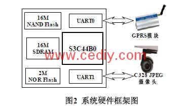
2. System structure We use the hardware framework shown in Figure 2. This system uses the S3C44B0 processor as the core: supplemented by 2M NOR Flash storage boot program, kernel, ROM file system; 16M NAND Flash carries the YAFF file system to make up NOR Flash lacks space to accommodate PPPD, system applications, and failure to save system configuration information; 16M SDRAM running code, dynamic data exchange, RAM file system; UART0 connects to CWT2000 GPRS module, used to send and receive messages that interact with users, and send MMS To the terminal specified by the user; UART1 connected to the C328 JPEG camera can directly obtain high-resolution image data in JPEG format.
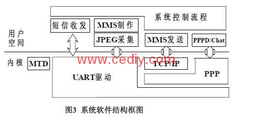
The software of this system is based on the uCLinux operating system kernel version 2.4.32. Figure 3 shows the software block diagram of this system. In Figure 3, the MTD, UART driver, TCP / IP, PPP, etc. in the kernel space must be selected when compiling the kernel. The PPPD / Chat dialer is used to log in to the Internet through the GPRS module. Some of the modules in the above software block diagram are included in the uCLinux distribution. Therefore, this system needs to implement JPEG acquisition, MMS production, MMS sending, SMS sending and receiving, and system control flow modules. The following chapters will introduce the implementation technology of each module.
3. Software Design This section will focus on the system control flow, JPEG acquisition, MMS production, and MMS sending module in Figure 3. Because the short message sending and receiving module is too simple, and has been introduced in detail in many materials, this article will not repeat them.
3.1 System control flow The system control flow module is responsible for calling other modules, coordinating all resources, realizing the work flow of system design, and satisfying good interactivity and stability.
First, the system needs to be initialized, such as obtaining the user terminal (mobile phone) number, the MMS gateway, port, and MMS center address required for the MMS sending process. These information are stored in the system configuration file, and some related data structures need to be initialized. After initialization, the system enters into a super loop, ready to receive short messages from the user terminal commands. At present, there are two command short messages, the most important of which is the "Get" command to obtain MMS information; there is also a "Set" command to set the user terminal number. This command is shown in Figure 4 due to the size of the flowchart Is omitted. After receiving the "Get" command, the system sequentially calls the JPEG acquisition module, MMS production module, GPRS dialing, and MMS transmission module. The calling of these modules, except for the MMS production module, all follow a basic principle, which we call the principle of three attempts. If the call of a certain module is unsuccessful, it will be repeated three times, and all three will fail, and an error report SMS will be sent to the user terminal. The special one is GPRS dialing. After 3 dialing failures, the GPRS module will be reset and then dialing will be attempted. This principle conforms to the particularity of wireless communication itself, and can effectively improve the efficiency and stability of the program. Another thing to note is that SMS cannot be sent under GPRS status. Therefore, after successful dial-up login, you need to disconnect the GPRS connection to send SMS. This is why no matter whether the MMS is sent successfully, you must first disconnect GPRS, and then send an error or successfully report a short message.
3.2 JPEG image acquisition The JPEG image acquisition module directly controls the C328 JPEG camera to acquire JPEG images through the serial port. This choice greatly reduces the burden on the processor. See reference [1] for the hardware information of the camera. Most of the software modules are sequential processes, and the following processes are based on the correct execution of the previous process. In general, it can be divided into three steps: initialize the S3C44B0 serial port, initialize the camera, and obtain images. The detailed process is as follows:
1. Initialize the S3C44B0 serial port, including: O_RDWR | O_NOCTTY | O_NDELAY to open UART1, which is "/ dev / ttS1" [2], set the baud rate to 57600, 8 data bits, 1 stop bit, no parity, read Set the write timeout to 1 second and initialize the jpeg_picture structure:
struct jpeg_picture
{
int fd; // File descriptor of the serial port
unsigned char resoluTIon; // image resolution code
long jpeglength; // 24-bit image length
unsigned char * pjpeg; // Image storage address
};
1 JPEG camera, including: send SYNC command to establish connection with the camera, send IniTIal command to set the output JPEG format image, resolution 640X480, send Set Package Size command to set the size of the data packet to 512 bytes.
2 Get images, including: send Snapshot command to capture image snapshot and compress, send Get Picture command to get Snapshot type image, receive Data command to confirm the data type is Snapshot and image data size, and allocate corresponding space for the image, then start receiving data packets, After each data packet is received, an ACK command with a data packet ID is sent to the camera until the last data packet ID is F0F0, and the data receiving process ends.
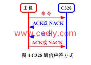
The communication protocol adopts a response mode as shown in Fig. 4, ACK represents the success of the last command or operation, and NACK means failure, ensuring stable communication. The command defined by C328 is a uniform length of 6 bytes, starting with a fixed 0xAA, then the command byte, and the last 4 bytes are the parameter bytes related to the command.
3.3 MMS production MMS can contain a variety of multimedia information such as static images, voices, dynamic images [3 4]. The left side of FIG. 5 is a general MMS structure, which is composed of an MMS information header and an MMS information body. The MMS message header contains information on how to send data from the sending terminal to the receiving terminal [5]. The MMS information body is the essential content of the MMS, and can be composed of multiple parts and multiple types of media. At present, there is only JPEG image data in this system, and there is no need to support multimedia information in all formats. Therefore, a simplified version of the MMS production module for multiple JPEG images can be realized. We used the most simplified MMS header, including: message type, transaction ID, version number, From, To, etc., see Table 1 for details. 
The MMS code must follow the Wireless Session Protocol (WSP). WSP uses the same syntax as HTTP / 1.1 to describe the organization structure of the data. For details, please refer to RFC [2068]. HTTP / 1.1 uses ASCII character encoding to transmit data, and WSP defines the character strings corresponding to some well-known fields in HTTP / 1.1 as one byte to reduce the transmission bandwidth, and adds 0x80 when encoding these compact formats, so that The encoding of well-known fields is greater than 127 (extended ASCII characters), thus distinguishing them from ordinary ASCII characters. Therefore, the basic encoding format of the MMS information header is: "domain encoding" + "content", please refer to Table 1 for details. The coding sequence is as follows: the message type, transaction ID, and version number must be ranked first, and the content type of the MMS message body should be ranked at the end of the MMS message header.

â‘ Use a character string to represent a random number. â‘¡The domestic format is: length + "+86" + "11-digit mobile phone number" + "/ TYPE = PLMN."
Immediately after the MMS message header is the MMS message body. The parts shown in Figure 5 are: number of members, members (images, text, sound, etc.). The number of members is a variable-length integer. The members of the MMS information body consist of: member information header and member data. Our system only has JPEG images, so the member information header can be encoded as: 0x01, YYYY (JPEG image size, variable length integer), 0x9E. Finally, attach the JPEG image to the member information header to complete the MMS production. Note that since the storage space of the image is dynamically allocated, the occupied memory should be released later.
3.4 MMS transmission Finally, the system uses the MMS transmission simplified process developed by the project team for embedded systems to send MMS messages. The simplified process is divided into three steps: establishing a connection, sending data, and disconnecting the connection [6]. Figure 6 shows the timing diagram of the simplified process of sending data. The timing diagram for establishing and disconnecting is similar to this and is not given here. In the implementation of this simplified process, an implementation method that directly constructs PDUs for transmission is used. The protocol data unit (Protocol Data Unit, hereinafter referred to as PDU) is a data header to be added by each layer when the MMS is sent, and many parts of these data headers are fixed. Therefore, by directly sending PDUs, you can avoid constructing a complete wireless application protocol stack (WAP), get rid of the dependence on multithreading, and the storage consumption required for irrelevant operations, and achieve single-threaded, efficient, high-speed, and stable MMS transmission. 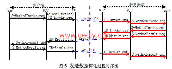
The simplified process of the network protocol stack relationship sent by the MMS only requires the embedded system to provide UDP support and can connect to the GPRS network to send the MMS to the terminal.
4. Conclusion and Outlook This system has passed the tests in Changsha, Shenzhen, Beijing, Shanghai and other places. The project makes full use of the characteristics of wide coverage of GPRS network and stable communication quality, and proposes a simple, convenient, stable, and easy-to-extend MMS-based security system framework, which provides a new method for extracting criminal evidence from criminal suspects. The framework has a wide range of applications and can provide references for related industries.
The author of this article innovates: combined with the simple operation of short messages and the intuitive characteristics of MMS, a MMS-based security system is implemented on the low-cost ARM7 platform; a direct PDU construction method is used in the system to implement a simplified version of the MMS sending process. This process is simple to implement and suitable for embedded systems.
Mirror Heating Elements can be used in many field. Such as car rearview mirror.bathroom mirror.camera even in flower showcase freezer.With the property of automatically power change,the PET heating film can convert the electrical energy into thermal energy efficiently which makes the mirror suface's temperature rise to prevent steam from condensing. Not only did we supply the good quality of manufactured goods but also offer service of custom-made mirror heating film.We look forward to build business cooperation with customers worldwide.
Mirror Heating Elements
Rearview Mirror Heating Film,Ptc Heating Film , Mirror Heating Elements,Bathroom Mirror Heating Film
ShenZhen XingHongChang Electric CO., LTD. , https://www.xhc-heater.com