
Design of wireless automatic meter reading system based on CC1100
Design of wireless automatic meter reading system based on CC1100
In recent years, the fastest growing and most widely used in the field of information communication is wireless communication technology. The wireless communication technology has a trend of integration, low power consumption and easy operation. Micropower short-range wireless data transmission technology is a practical technology for wireless communication. It generally uses a single-chip RF transceiver chip, plus a microcontroller and a small number of peripheral devices to form a dedicated or general wireless communication module. Basic data wireless short-range meter reading function. This paper presents a wireless automatic meter reading system based on CC1100, which has good communication quality, low cost, reliable operation, economical and practical, can accurately and timely copy the user's three meter data, is an ideal automatic meter reading solution The plan is also the development trend of meter reading charging system.
1 Meter reading system structure
The meter reading system is mainly composed of the main station, GPRS communication channel, concentrator, low-voltage power line network, data collector, and user electricity meter. The working principle of the system is to use low-voltage power line or RS-232 bus to transfer the meter data from the collector to the concentrator, and then the concentrator transmits the signal to the GPRS network in time or in real time. At the end of the data exchange, the computer of the master station finally receives the data on the Internet and performs related processing such as user meter data collection, electricity fee measurement, and line loss analysis.
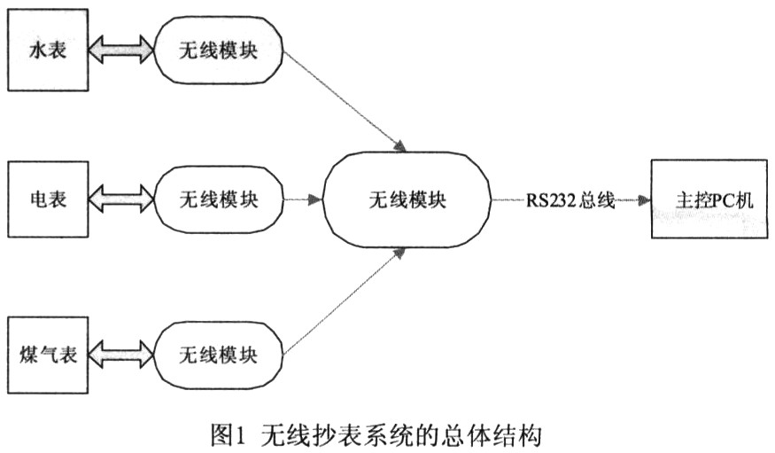
The system can be used to copy three or more tables of data within the home. The lower layer of the system is directly connected to water meters, electricity meters, gas meters, etc., and the upper layer is connected to the host of the meter reading center to realize remote copying of data. The system generally uses passive meter reading. When the upper module receives the meter reading command from the instrument center, it sends the meter reading command to the lower module wirelessly. The overall framework of the wireless meter reading system is shown in Figure 1.
2 Introduction of main devices
2. Main features of 1AT89S52
A89S52 is a low-power, high-performance CMOS 8-bit microcontroller with 8k in-system programmable F1ash memory. The on-chip F1ash allows program memory to be programmable in the system and is also suitable for conventional programmers. On a single chip, with a clever 8-bit CPU and in-system programmable Flash, AT89S52 provides a highly flexible and ultra-effective solution for many embedded control applications.
A89S52 is compatible with MCS-5l single-chip products, with 8k bytes in-system programmable F1ash memory, 1000 erase and write cycles, full static operation: OHz ~ 33Hz, three-level encryption program memory, 32 programmable I / O lines, Three 16-bit timers / counters, eight interrupt sources, full-duplex UART serial channel, low-power idle and power-down modes, wake-up after power-down interrupt, watchdog timer, dual data pointer, power-down Identifier.
2. The main performance of 2CC1100
CC1100 is a low-cost true monolithic UHF transceiver designed for low-power wireless applications. The circuit is mainly set to the ISM (industrial, scientific and medical) and ISRD (short-range equipment) frequency bands at 315, 433, 868 and 915MHz, and can also be easily set to 300-348MHz, 400-464MHz and 800-928MHz Other frequency bands. The RF transceiver integrates a highly configurable modem. Its data transmission rate can reach 500kbps. By turning on the forward error correction option integrated on the modem, performance can be improved. CC1100 provides extensive hardware support for packet processing, data buffering, burst data transmission, clear channel evaluation, connection quality indication, and electromagnetic wave excitation. The main operating parameters of CC1100 and 164-bit transmission / reception FIF0 (first-in first-out stack) can be controlled through the SPI interface.
3 hardware design
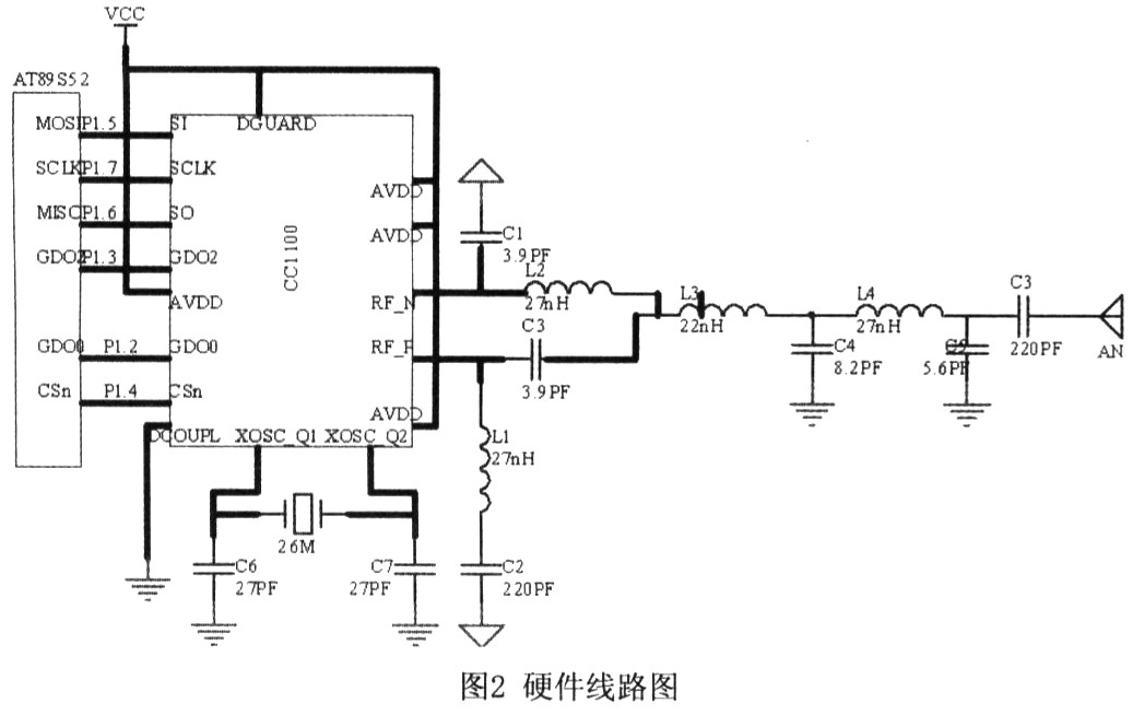
The control of the transmitting module and the receiving module by the single-chip microcomputer must first initialize the interface of the single-chip microcomputer (SPI bus interface technology is a high-speed and high-efficiency serial interface technology, which is mainly used to expand peripherals and perform data exchange.), Then we need to initialize the RF module. In this part of the initialization, we need to power on the chip and configure its on-chip registers. The transmitter first transmits a set of data through the mouth pair, the buffer sets the number of data to be sent at a time, then writes the data packet to be sent, the data is automatically added with the preamble and check, and then enters the sending mode to send the data packet, Wait for the end of this transmission, and finally flush the buffer, this time the transmission is completed. After receiving a set of data, the receiving end first enters the receiving mode, waits for the completion of the received information, then the received data packet is decomposed, all the received data is read out and stored, and finally the buffer is cleaned. This time the reception is completed. CC1100 has many features such as packet processing mechanism, sending and receiving FIF0, WOR mode (WakeonRadio) and so on. The wireless transceiver chips before CC1100 used synchronization to send the data out bit by bit. This method is more troublesome to handle when sending and receiving data, and the preamble and synchronization words must be judged when receiving. CC1100 undertakes these tedious tasks. When you need to transmit data, you only need to write the transmitted data to the transmit FIF0 through the SPI port according to a certain format, and then configure the CC1100 to transmit, and the data will be transmitted as required. ; When receiving data, first configure CC1100 to receive state. Once the data that meets the requirements is received, CC1100 will store the received data in the receiving FIF0, and a pulse will appear on pin GD00 or GD02. This pulse It can be used to notify the MCU that a data packet has been received by the CC1100, and the MCU can retrieve the data received by the CC1100 through the SPI port. The hardware connection is shown in Figure 2.
4 software design
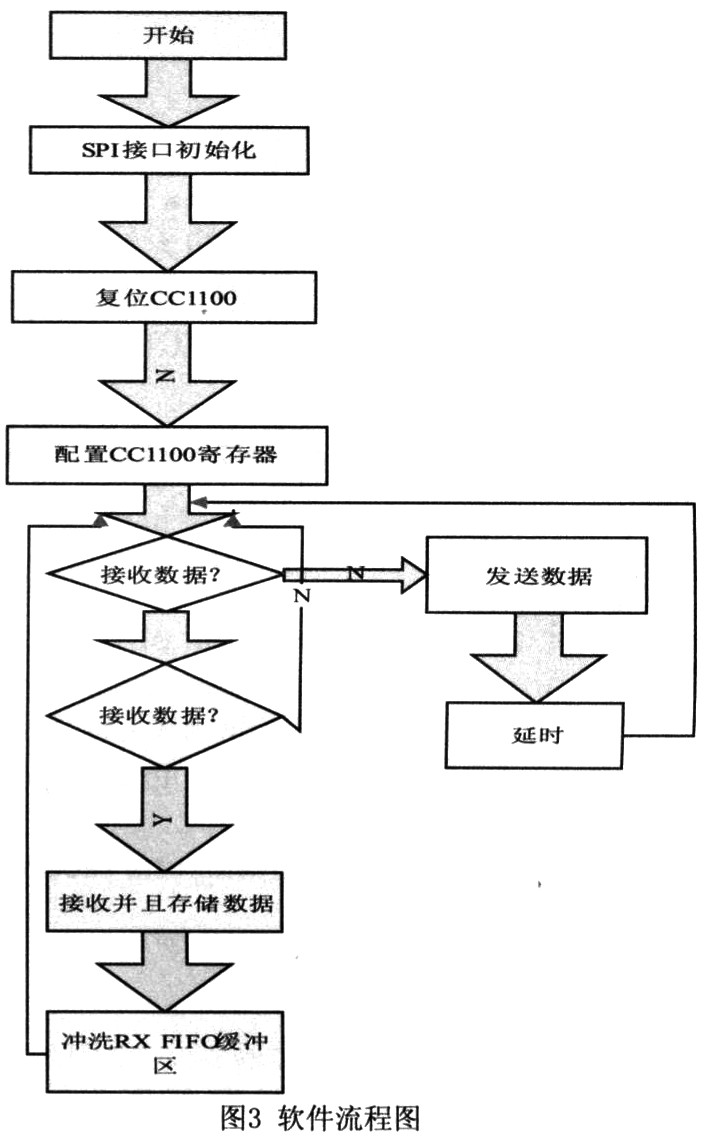
CC1100 is configured through a 4-wire SPI compatible interface (SI, S0, SCLK, and CSn), which is used for both writing and buffering data. The SPI interface is a synchronous serial communication interface, and CSn is the chip selection pin. When the pin is low, the SPI interface can communicate, otherwise it cannot communicate. SI and SO are digital transmission pins, used for data input and data output, respectively. SCLK is a synchronous clock, and digital data is written or read at the rising or falling edge of the clock. When reading or writing a register, first write the register address (Address) byte on the SI pin. The address byte has 8 bits, the highest bit is the read-write bit, and the last 7 bits are the address bits. When the register write operation is performed, the read-write bit is 0, and when the register read operation is performed, the read-write bit is 1. Whether it is a read operation or a write operation, when the address byte is written, a chip status byte is output on the CC1100S0 pin. The status byte contains the key status signal, which is useful for the MCU. CC1100's TXFIF0 (transmit first-in first-out stack) and RXFIF0 (receive first-in first-out stack) can also be accessed using the same read-write method, except that the address segment is different from the configuration register. In addition, CC1100 commands are also transmitted through the SPI interface, CC1100 has 14 internal commands. These commands are used to turn off the crystal oscillator, turn on the transmission mode, state transition and electromagnetic wave activation. The software flow is shown in Figure 3.
Write specific bytes through SI to make CC1100 execute different commands. CC1100 has 20 pins, which can be configured through 4-wire SPI compatible interface (including data lines SI, S0, clock line SCLK, and enable line CSn). Among them, CSn can be connected to an IO port to simulate the timing, while the other three pins are connected to the SPI interface of the main MCU. By repeatedly using SI, SCLK and CSn on the SPI interface, the main state of the communication can be performed with a simple three-pin control, namely sleep, idle, RX and TX. CC1100 has two dedicated configuration pins and a shared pin, which can be used to output internal status information useful for control software, and can be used to generate interrupts to the MCU. Its pin names are GD00 and GD01. The shared pin is the S0 pin on the SPI interface. The default setting of GDOl / SO is 3-state output. By selecting any other control option, the GD01 / SO pin can be made into a general pin. When CSn is low, this pin functions like the general S0 pin; while in synchronous and asynchronous continuous mode, in the transmission mode, the GD00 pin is used as a continuous TX data input pin.
5 Conclusion
The wireless automatic meter reading system is an inevitable trend for future development, and for the transformation of the meter reading system, the wireless automatic meter reading system composed of the AT89S52 microcontroller and CC1100 has the advantages of convenient use, low cost, flexible application, and moderate price. The three tables in the family can be copied together. It can also be used in low-power remote sensing surveys, residential and building automatic control, wireless alarm and security systems, industrial monitoring and control, wireless sensor networks, remote control telemetry systems, and is suitable for consumer electronics, residential, building automatic control, etc. Wireless applications.
Depending on your location and budget Street Lighting Pole may include structures which are crafted from steel, aluminum, cement, wood or fiberglass.
Street Pole, street Lighting Pole
material: steel,Q235,SS400.
type:conical, octagonal, or polygonal ,mid-hinged ,taped and other shapes.
height:3-30m
Thickness:2-6mm
surface treatment: hot dip galvanization or hot dip galvanization and powder coated.
arm: single arm,double arms ,three arms or four arms.
Application: street ,road ,highway, park ,factory ,school and so on.
power souce: high pressure sodium light , metal halide light or flood light.or energy saving light.
Street Light Pole,Steel Lamp Pole,Street Pole,Street Lighting Pole
YIXING FUTAO METAL STRUCTURAL UNIT CO.,LTD( YIXING HONGSHENGYUAN ELECTRIC POWER FACILITIES CO.,LTD.) , https://www.chinasteelpole.com