
Design of interactive set-top box based on STB5660 solution
Design of interactive set-top box based on STB5660 solution
Abstract: From the aspects of system function, logic structure, hardware and software, the design scheme of interactive set-top box system based on STB5660 solution is discussed.
1 Introduction
Information dissemination mainly includes three major network systems: communication network, radio and television network and computer network. With the rapid development of communication technology, television technology and computer technology, the three major networks have entered a new era of mutual integration. Interactive TV (ITV) is the embodiment of this combination. The so-called interactive TV is a video distribution service controlled by the audience. In the program and within the program, the audience can make their own choices and decisions. It is a new type of TV technology with asymmetric duplex communication mode. Among them, the digital set-top box (STB) is one of the key technologies to realize the interactive function. By sitting in front of the TV at home, STB viewers can realize various services such as video on demand (VOD), home shopping, home office, electronic games, and can also watch high-definition digital TV programs sent by TV stations on ordinary TVs. .
2 System function plan
The system functions are based on PHILIPS 'STB5660 solution (SAA7214 + SAA7215 + UAD1320A). It can provide functions including QAM signal reception, demodulation, video and audio processing, and user interface. The system adopts a highly open modular structure design. The front end of the system compresses the analog video and audio signals into digital signals through MPEG-2 video encoding. After multiple channels of digital signals are multiplexed by a multiplexer, QAM modulation is transmitted. As the user's downstream digital signal. The user uses the telephone DTMF or BPSK as the uplink, and can transmit the information selected by the user to the system service center (system front end) through the uplink channel. In this way, interactive video on demand (VOD), stock information and analysis and timely transactions, distance education, information transmission and other functions can be realized in the broadband network (that is, the cable TV network).
3 System logical structure
According to the basic functions of STB, STB can be divided into six layers according to the logical level, as shown in Figure 1.
Physical layer: full channel tuning reception and demodulation. The QAM modulated signal transmitted from the HFC network can be demodulated.
Link layer: Convolutional decoding / deinterleaving, REED SOLOMON decoding, energy dispersion and migration. The QAM demodulated signal is processed to generate a data stream that conforms to the MPEG-2 / DVB standard.
Transport layer: demultiplexing and data unpacking. Separate the generated data stream into video packets, audio packets and data packets, and transmit them to the corresponding chip for processing.
Conditional access layer: controls the operation of the descrambling function. In the set-top box, there is a corresponding permission confirmation function. When the set-top box receives the permission confirmation information, it decodes the digital TV program for the user to watch.
Service layer: video and audio decompression, EPG (electronic program guide) generation and data decoding. Decode and encode the received data stream for video, audio and graphics.
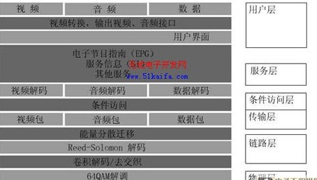
Figure 1 System logic structure
User layer: contains user interface display, conversion, remote control operation, etc. The demodulated, decoded, and encoded video and audio signals (that is, analog signals) are output from the corresponding ports of the set-top box. At the same time, the remote controller can be used to control and switch all basic functions.
4 System hardware structure scheme
According to the STB5660 solution and the functional characteristics of the IC chip, the hardware structure of the system is proposed, as shown in Figure 2.
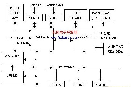
4.1 Front-end decoding part
The front-end part accepts the signal output from the cable TV cable, after tuning frequency conversion, QAM decoding, de-interleaving, de-RS code, descrambling, etc., it outputs the standard code stream before MPEG-2 demultiplexing, that is, the transport stream (TS stream ). This part is mainly completed by a VES1820X chip.
4.2 Transport stream and video and audio decoding
Transport stream and video and audio decoding parts are completed by SAA7214 and SAA7215 chips. Among them, SAA7214 is responsible for decoding the MPEG-2 source of the TS stream, and separating the video and audio data streams, as well as the control of peripheral I / O devices associated with the decoding. SAA7215 is responsible for the decoding and encoding of audio, video and graphics, and divides the decoded data stream into audio and video signals. SAA7215 also has a perfect memory structure, using DRAM, SDRAM, FLASH, etc., through these memory chips to greatly speed up the software.
4.3 Back-end decoding part
Back-end decoding is done by SAA7215 and UDA1320A. The video signal is output by SAA7215. The audio signal is output by UDA1320A. UDA1320A is a single-chip normal-phase stereo DAC with bit data stream conversion technology. It has low power consumption and low voltage operating mode; it has three different frequency system clocks of 256, 384 and 512; through static pin control, you can choose different Frequency; supports sampling frequencies from 16KHZ to 48KHZ; integrated digital filtering and normal phase DAC.
4.4 Network interface for interactive applications
The interactive application hardware implementation part is completed by SAA7214 and the responding network interface.
4.4.1 Telephone network connection using ADSL technology
Telephone network connection using ADSL technology: The set-top box connects the smart card interface and the ADSL Modem through the peripheral serial port, and the parallel port is used to transfer data between the set-top box and the PC. The ADSL Modem is directly connected to the ADSL central office through a telephone line, which can provide high-speed data communication with a downlink rate of 8 Mbits and interaction of user control information with an uplink rate of 640 kbits. Through ADSL, the set-top box has a faster rate than its direct Internet access, thus achieving high-speed interactive services with the ATM / OP network.
4.4.2 Hybrid network connection using optical fiber / coaxial cable technology (HFC)
Hybrid network connection using optical fiber / coaxial cable technology (HFC): HFC downstream uses a digital tuner demodulator to convert the signal of the user's selected channel into a baseband data stream; upstream uses a modulator to send the user's control signal into the channel , Its interface also uses a cable modem.
5 System software solution
The software structure of the set-top box system can be divided into three levels: business software application layer, real-time event processing layer, system kernel and driver layer. The system software structure is shown in Figure 3.
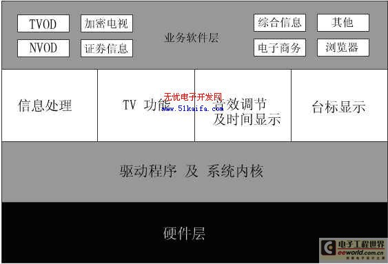
5.1 Business software application layer
The business software application layer is a layer of interfaces covering the driver and the operating system. It is formulated according to the business needs of the system and serves various functions of the set-top box for user applications. Such as comprehensive information, e-commerce, video games, etc.
5.2 Real-time event processing layer
The real-time event processing layer is a software environment that isolates applications from low-level operating systems and hardware details. It makes applications independent of specific hardware platforms. It is a middleware between business software applications and hardware platforms. This software system Using OpenTV middleware. OpenTV middleware provides a complete application program interface for user applications, so that applications only need to call these functions to achieve all the functions that a set-top box system should have. In this way, the work of the user application part becomes very simple.
5.3 System kernel and driver layer
The operating system used in this system is pSOS, the hardware driver layer is mainly for various hardware modules, providing corresponding drivers. The main drivers include: interface module, including I2C interface operation control, smart card control, etc .; audio module; video module; demultiplexing module; decoding module, Flash drive module, etc.
6 Conclusion
The above describes the logical structure, system functions, system hardware and software composition and implementation of the interactive digital TV set-top box based on the STB5660 solution. At present, the domestic broadcast and television system has begun to change to digital TV. Although more recent digital applications are still digitizing analog color TV sets, with the increase of users 'functional requirements and the richness of cable operators' service content, there are many Functional interactive digital TV set-top boxes will also be increasingly used.
625nm LED is a red LED. Common red LEDs are like: red 620nm LED, Red 625nm LED, red 627nm led, red 630nm LED and so on.
We supply variety of 625nm red LED products. Including Through-hole 625nm LED, SMD 625nm LED and high-power 625nm LED. We can also produce 625nm LED according to your requirement.
For the Through-hole Light Emitting Diode 625nm LED,
we can customize the shape, the lighting angle, the number of emitting source, the flat pin LED and braided LED. Such as: 5mm red 620nm LED, 5mm red 630nm LED,5mm red 627nm LED, 5mm red 625nm LED. 3mm red 620nm LED, 3mm red 625nm, 3mm red 627nm LED, 3mm 630nm LED.
There are many other shapes for your choose. Customized red LED are available
For the SMD LED 625nm LED,
we can supply dual-chip red LED, three-chip red LED, multi-chip red LED, high voltage LED, flashing red LED and variety of size SMD LED. For instance: 3528 SMD red 620nm LED, 3528 SMD red 625nm LED, 3528 SMD red 627nm LED, 3528 SMD red 630nm LED. 2835 SMD red 620nm LED, 2835 SMD red 625nm LED, 2835 SMD red 627nm LED, 2835 SMD red 630nm LED.
There are also have many other shapes to choose, like the 5050 SMD red LED, the 5730 SMD red LED ect. You can choose any one of them for your requirement.

We will do the High temperature resistance testing and 10 hours ageing treatment before the product out off the factory, which can ensure the stability of each product.
Our LED products have 5 year warranty.
We are the best supplier for your light-emitting diode.
625nm LED
625nm LED, 3W 625nm LED, SMD 625nm LED, Red 625nm LED, 625nm High Power LED
Shenzhen Best LED Opto-electronic Co.,Ltd , https://www.bestsmd.com