
How to Use Programmable Logic Device PLD to Connect High Speed ​​Video Content to Video Players
From portable media players and mobile phones to video game consoles, the rapid growth of consumer video applications requires a large number of different interfaces and adapters to enable users to transfer video data between their computers and various entertainment information devices.
Common consumer video interfaces include IEEE 1394 (Firewire), USB 2.0, DVI, HDMI, and a variety of wireless standards. This article describes how to use Programmable Logic Devices (PLDs) to connect different high-speed video content to video players.
Video input
USB 2.0 is currently the mainstream high-speed video standard for connecting computer and entertainment information devices. USB 2.0 uses NRZI encoding with a bandwidth of 480 Mb/s. From digital cameras, set-top boxes, information appliances, to MP3 players, PDAs, game consoles, and 3G phones, each device has one or two USB 2.0 ports.
The USB host device can supply power to its external devices. It can provide up to 500mA and 5V power on a 5m cable and can support up to 127 external devices. The digital TV (DTV) tuner is equipped with a USB module, and if the user connects it to a laptop, then TV programs can be watched on the go.
Standard-definition video decoding has a data transfer rate of up to 8 Mb/s, while high-definition video decoding requires a transfer rate of 55 Mb/s, which is much lower than the USB 2.0 transfer rate. A low-cost ASSP master/device USB controller can be used as a video PHY interface. The output can be sent to the PLD for data processing via the parallel bus. For further integration, a USB MAC (Media Access Controller) can be designed into the PLD.
Parallel video data can be sent to the final video decoder for playback via the multiplexer. The USB 2.0 PHY chip can be easily connected to any of the PLD's I/O pins. Most PLD I/O pins can be programmed for 3.3, 2.5, 1.8, or 1.5V LVTTL/LVCMOS.
IEEE 1394 uses full-duplex 8b/10b encoding and can transmit up to 400 Mb/s. The FireWire interface can operate without a host device for point-to-point communication. The cable can be up to 4.5m long and supports up to 63 devices. For connected devices, 1.25A, 12V power supply is available. The low-cost physical layer ASSP can be used as an interface with the PLD to further enhance data processing.
Video output
Both DVI and HDMI are based on the Minimized Transmission Differential Signaling (TMDS) channel, which uses 8b/10b encoding. Class A HDMI is backward compatible with DVI-D, which only transmits digital signals. This means that with a suitable adapter, the DVI output can drive the HDMI monitor and vice versa, but the HDMI audio and remote pointing functions are not available.
Class B HDMI is backwards compatible with the dual transmission channel DVI. High-bandwidth Digital Content Protection (HDCP) is a technology for protecting digital entertainment content that prevents end-users from viewing or copying restricted content. Most HDMI interfaces support the HDCP specification, but most DVI do not support HDCP.
A variety of existing DVI and HDMI PHY chips can interface directly with the PLD. PLDs usually provide processing and enhancement of images such as de-interlacing, color space conversion, and 2D filtering. These are the perfect applications for today's PLDs for large logic cells, DSP blocks, and flash memory.
Most consumer electronics products provide I2C interfaces for control and configuration.
There are many reference designs that can be downloaded and reused. The VHDL language optimized for Altera's PLD product line has its I2C controller. In the design, the register address of the VHDL source file is all defined as a constant, and the designer can simply customize it. The address of the memory base address register is defined as a generic parameter, which can also be easily modified and customized. One pin in this design gives an output indicator signal that can be used by the MCU as an indicator when I2C data transmission is complete.
System Application Example
Most PLDs can accept digital video sources in different formats and protocols. PLD will input formatted video data into the 10b CCIR 656 standard parallel video bus, so that these video streams can be played through the existing digital encoder (DENC) chip. This bus can be gated or multiplexed to the DENC.
The PLD application diagram shown in Figure 1 connects a digital video source to video playback. A typical high I/O pin density PLD can accommodate parallel video data from the PHY chip.
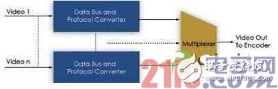
Figure 1 PLD can connect digital video sources to video playback
Different data buses input from interfaces such as USB and IEEE 1394 must first enter the general-purpose I/O pins. The second step is to transfer the parallel video data to the generic video bus to allow multiplexing or strobing for playback. The I2C reference design is used to control the configuration of PLDs and onboard ASSPs.
Figure 2 shows the block diagram of the entire system, including the connection of the video PHY chip to the PLD. The output of the PLD generates the CCIR 656 video format data and enters the existing video encoder via the bus. The I2C reference design can be used to control all PLDs and standard chips.
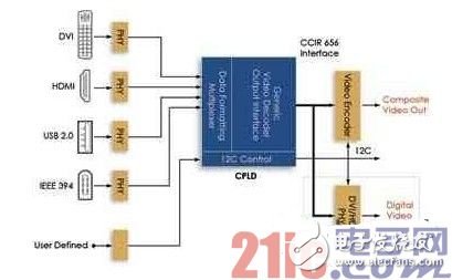
Figure 2 Video PHY chip generates CCIR 656 video signal via PLD
Railway insulator,Insulator fittings,Epoxy fiberglass rod,Composite insulator
TAIZHOU HUADONG INSULATED MATERIAL CO.,LTD , https://www.thim-insulator.com