
IF Transmission Technology of Satellite Communication Analog Source Based on Software Radio
O Introduction
Software radio is a brand-new architecture based on broadband analog-to-digital / digital-to-analog conversion devices and high-speed digital signal processing chips, with software as the core (Software-Oriented). The development of software radio technology provides a good basis for the development of satellite communication systems. Because FPGA has a high degree of flexibility and reconfiguration, it is more and more widely used in software radio-based communication systems. The design is based on software radio, adopting FPGA to realize all-digital modulation general satellite signal source module. The data protocol and modulation mode are arbitrarily variable, and can be flexibly applied to various satellite communication systems.
1 Hardware system design
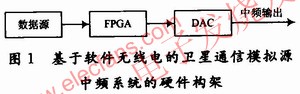
Software radio technology requires the use of broadband digital-to-analog / digital-to-analog converters as close to the antenna as possible to complete the digitization of the signal as early as possible, so that the functions of the radio station are defined and implemented as much as possible with software. However, due to the technical limitations of broadband antennas, high-speed A / D, D / A, and DSP, the conditions for implementing an ideal software radio platform are not yet available. Therefore, the current research on software radio is focused on the above-mentioned key technologies, on the other hand, it is more on the existing technical conditions to study how to maximize the versatility and flexibility required by software radio To embody software-based and generalized design ideas into specific application practices. Although the implementation of the direct radio frequency transceiver system based on software radio is still somewhat difficult, the intermediate frequency transceiver technology based on intermediate frequency digital signal processing is quite mature. This satellite communication simulation source adopts software radio-based intermediate frequency transmission technology, and uses high-speed DAC and high-end FPGA as the hardware carrier to give the output of analog intermediate frequency signal. The block diagram of the system structure is shown in Figure 1 (the complete transmission system also requires mixers, amplifiers and welcome to reprint. This article comes from the electronic enthusiast network (http: //) antennas, etc., which is not within the scope of this article), FPGA data After being coded and modulated, it is sent to the DAC to generate an intermediate frequency output.
The satellite communication analog data source can be generated either inside the FPGA or externally. In order to ensure the versatility of the hardware platform, the external interfaces of the satellite communication analog source system have TTL, 422 and LVDS types, which are used to meet various interface requirements. FPGA is the core device of the entire system. In order to ensure the processing speed and the capacity of the logic unit, the Altera Str-aTIx II series FPGA-EP2S90F1020 is used. EP2S90F1020 has 72 768 registers and 72 768 arithmetic look-up table units, 4 Mb memory units and 384 9 b multipliers. It has a fast working speed and very rich resources. It can perform most of the digital intermediate frequency processing operations internally. .
In order to ensure the quality of the intermediate frequency output signal, the sampling clock of the DAC is preferably greater than or equal to 4 times the carrier frequency. If the carrier IF is 70 MHz, the sampling clock of the DAC should be 280 MHz or higher. Considering the programmability and upgradeability of the system, AD9736, an ultra-high-speed DAC from Analog Devices, is used. The data accuracy of the AD9736 is 14 b, the sampling rate is up to 1 200 MSPS, the DDR mode LVDS data receiver is adopted, the current type output, and the built-in synchronous control circuit are suitable for application in the broadband communication system.
Due to the high operating frequency of the hardware system, high-speed circuit design methods are required, and the following points need to be noted:
Signal integrity requires signal integrity simulation of the board-level system, pay attention to impedance matching, reduce crosstalk between key signal lines, and control the delay between data buses;
Power integrity requires a power integrity simulation of the board-level system, increasing the margin of the maximum current that can be passed on the lines and vias, and adding decoupling capacitors at appropriate locations to reduce the AC impedance on the power and ground planes;
Electromagnetic compatibility Because the hardware belongs to a mixed analog / digital circuit, you need to pay attention to the isolation of the analog part and the digital part when wiring. Use independent analog power and digital power, as well as analog ground and digital ground, especially pay attention to reduce the interference of the digital part to the analog part ;
Power consumption issues As the operating frequency of the system increases, the power consumption of the system also increases, and key components need to be cooled.
2 Software system implementation
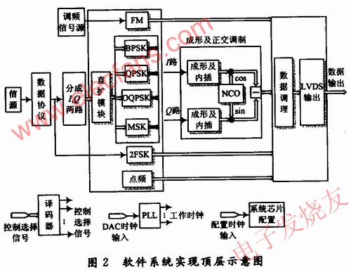
The software system mainly includes modules such as chip configuration, data protocol, baseband data modulation, interpolation shaping filtering and quadrature modulation. The chip configuration module mainly initializes and configures DAC and other chips, and sets its working mode. The data protocol module defines the structure of the data packaged into frames, and the protocol corresponds to the modulation method. The baseband data modulation module contains the realization of various baseband modulation methods, such as BPSK, QPSK, OQPSK, MSK and BFSK. The interpolation shaping filter module is responsible for performing interpolation shaping filtering on the baseband modulated data to meet the needs of the system bandwidth and data rate. The quadrature modulation module mainly performs digital up-conversion (DUC) processing on I / Q data. The choice of modulation method and data protocol can be realized by the decoder. The specific software system is shown in Figure 2.
The source data is encoded into frames and serial / parallel converted according to the data protocol and sent to the baseband modulation module. Three typical protocols (ISOHDLC, ANSI ADCCP, and JBll98.1A-2004) are initially selected here. ISO HDLC is a high-level data link control protocol (HDLC) developed by the International Organization for Standardization (ISO) for bit procedures. The basic structure of the ANSI ADCCP protocol frame is basically the same as ISOHDLC, the main difference is that the generator polynomial of the frame check sequence field (FCS) of the former is
The I / Q data is selected in the direct spreading module or not. The PN code used for spreading is an m-sequence generated by the cascade of shift registers. The information data and the PN code can be directly XORed to achieve spreading.
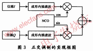
For digital phase modulation methods (such as BPSK, QPSK, and OQPSK, etc.), the data is shaped and interpolated and then quadrature modulated to the intermediate frequency. Its implementation follows the basic theory of software radio modulation, as shown in Figure 3.
In order to limit the signal spectrum to a reasonable range, the signal needs to be shaped and filtered. The square root raised cosine roll-off filter is the most commonly used shaping filter in wireless communication, which can eliminate the difficulty of ideal low-pass filter design. The transition band is smooth, and the shape of the transmitted signal can be changed by introducing a roll-off coefficient to reduce the impact of sampling timing pulse errors. After the baseband signal is shaped and filtered, before digital up-conversion, in order to increase the sampling rate of the signal, the input signal needs to be interpolated, and a filter is needed to filter out high-frequency images. The shaping filter and interpolation filter can be combined into a FIR filter, and the coefficients can be generated by the rcosine () function in Matlab. The filter coefficients can be stored in the ROM of FP-GA and read out in the form of a look-up table when in use. Since the data is single-bit serial input, the shaping interpolation filtering operation is only the addition and subtraction operations between the filter coefficients, without multiplication Operation. This not only improves the processing speed of the system, but also saves multiplier resources.
In theory, all kinds of communication signals can be implemented with orthogonal modulation methods. According to Figure 1, the time domain expression can be written as:
Where: fc is the carrier frequency. The information of the modulation signal is contained in I (t) and Q (t), and the I / Q data under various modulation methods is generated by the baseband data modulation module. Since all kinds of modulation signals are implemented in the digital domain, the above formula should be digitized when the digital domain is implemented:
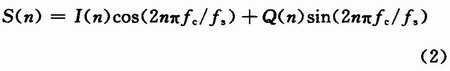
Where: fs is the sampling frequency. When the sampling frequency is 4 times the carrier angular frequency, the cos and sin terms in equation (2) become 0 or ± 1, which eliminates the need for mixing multipliers and numerically controlled oscillators (NCO), which greatly simplifies the modulation module.
NCO plays a very important role in the software system. It can not only generate LO signals for mixing, but also output FM and FSK modulated signals. A commonly used method to achieve NCO is to use the coordinate rotation digital calculation method (CORDIC) algorithm. The basic idea of ​​CORDIC is to use the successive approximation algorithm to calculate the trigonometric function. Its advantage is that it only performs addition and subtraction operations and shift operations. Combined with parallel processing and addition pipeline, it can achieve the output of an n-bit iteration every clock cycle . The basic function of the NCO module is to generate sine and cosine component outputs by phase control words. The data source controls the phase control word of the NCO to generate FM modulated data. The data source controls the NCO phase control word to switch between two constant frequencies, which can generate 2FSK modulation
制 æ•°æ®ã€‚ System data.
3 Index testing of analog sources
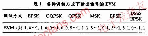
Agilent's vector signal analyzer 89641A can analyze various analog and digital modulation signals. As a receiver, it can display various information of the modulation signal (such as time-domain waveform, frequency spectrum, and constellation diagram, etc.). As a test instrument, it can quantitatively analyze the measured signal. The modulation accuracy of the signal (such as EVM, phase error and carrier frequency error, etc.). Using 89641A to test the intermediate frequency output signal of the satellite communication analog source, the vector amplitude error (EVM) under different modulation methods is shown in Table 1. It can be seen that the EVM indicators under various modulation methods are good. At present, the signal source has been successfully applied
To a certain satellite communication system, it works normally.
4 Conclusion
The satellite communication simulation source based on the software radio architecture is based on the basic theory of software radio and FPGA as the basic implementation platform. It has strong applicability and compatibility, and can be upgraded according to user requirements without changing the hardware. The reliability is high. It can be applied not only to the national defense military (such as military satellite communications and electronic warfare systems), but also to all aspects of national production in peacetime (such as GSM, satellite TV, 3G communications, etc.), with great economic benefits and promotion The value has a huge role in promoting and developing radar communication integration technology and satellite countermeasure technology, and has good social benefits. Welcome to reprint, this article comes from the electronic enthusiast network (http: //)
Glass Jar Food Blenders are stronger, which can crush ice. Glass jar food blenders' motors are more powerful, usaully use 7025 or 7030 motor. Their power can reach to 350/450W. Glass jar food blenders always with 6 pcs ice crushing blades and coffee grinder.
Discription of Glass Jar Food Blenders
Size: 1.25L, 1.5L
Controls Type: Rotary switch, push button
Packing: 4pcs/ctn(standard box)

Glass Jar Food Blenders
Glass Jar Food Blenders,Glass Jar Blenders,Blender With Glass Jar,Glass Blender
Flying Electronic Co., Ltd , https://www.flyingelectronic.com