
Working principle of Class B amplifier
How Class B Amplifiers Work Figure 9.6 shows a comparison of the output and input waveforms of a class B amplifier on the time axis.
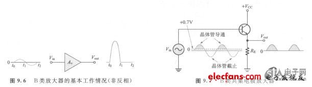
The class B amplifier is biased at the cutoff point, so ICQ = 0 and VcsQ = VCE (cutoff). When the input signal makes the transistor into the on state, the transistor will leave the cut-off point and work in the linear region. This situation can be illustrated by the emitter follower circuit in Figure 9.7. We can see that the output waveform is not the same as the input waveform.
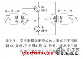
2. Working principle of push-pull amplification of class B We have seen that the circuit of Figure 9.7 is only turned on during the positive half of the input signal. To perform the amplification function during the entire cycle, a Class B amplifier that is turned on in the negative half cycle must be added. The combination of two Class B amplifiers working together is called push-pull operation.
There are two ways to use a push-pull amplifier to generate the entire waveform at the output. The first way uses transformer coupling. The second method uses complementary symmetry transistors (complementary symmetry transistors); that is, a pair of paired NPN1PNP BJTs, or a pair of N-channel or P-channel FETs used in conjunction with each other.
(1) Transformer coupling The transformer coupling circuit is shown in Figure 9.8. The secondary coil of the input transformer has an intermediate tap, which is connected to the ground, thus causing the two ends of the secondary coil to be opposite to each other. Therefore, the transformer converts the input signal into two signals with opposite phases, and then provides them to the two transistors. Please note that both transistors are of the NPN type. Because the signal phases are reversed, Qi will turn on in the positive half cycle and Q2 will turn on in the negative half cycle. Although one of the two transistors is always in the off state, again using the primary coil with the center tap, the output transformer can combine the output signals of the two transistors. The positive supply voltage is connected to the center tap position of the primary coil of the output transformer.
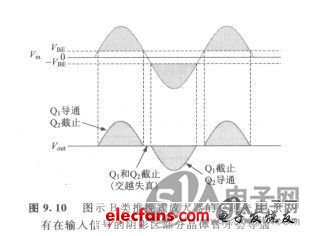
(2) Complementary symmetrical transistors Figure 9.9 shows the most common form of class B push-pull amplifier, which uses two emitter followers and two power supplies with positive and negative voltages. Because one emitter follower uses NPN transistors and the other uses PNP transistors, the two are turned on in the opposite half of their respective input cycles, so they are complementary amplifiers. Please note that no DC bias voltage is applied to the bases of the two transistors, that is, VB = 0. Therefore, the signal voltage is directly used to drive the transistor into a conducting state. During the positive half of the input signal, Q1 turns on; during the negative half of the input signal, Q2 turns on.

(3) Crossover distortion When the base DC voltage is zero, both transistors are turned off, and the input signal voltage must exceed VBE before the transistor is turned on. Because of this, during the alternation of the positive half cycle and the negative half cycle of the input signal, there will be a period when no transistor is turned on, as shown in Figure 9.10. The distortion of the output waveform caused by this is called crossover distortion (crossover distorTion).
In-Ear Wired Earbuds,Earphones With Mic,In-Ear Noise-Isolating Earbuds,Wired Earphones With Microphone
Dongguang Vowsound Electronics Co., Ltd. , https://www.vowsound.com