Speedometer design based on stepper motor driver MC33991
Compared with the analog circuit electronic instrument, the stepper motor type instrument has uniform indexing, good repeatability of the pointer, fast response, small jitter, stable quality and reliability of the product quality [1], so stepping Motor-type automobile instruments are gradually popularized in China. Such automotive instruments usually use a microcontroller to drive a stepper motor to drive the meter pointer to rotate. The microcontroller controls the stepping motor generally needs an external driving circuit, and the special automobile instrument stepping motor driving integrated circuit can simplify the software and hardware design of the automobile instrument and improve the stability and reliability of the instrument. This paper introduces and compares the performance characteristics of commonly used drives in China. Finally, the speedometer is designed with the MC33991 produced by Freescale Semiconductor as an example.
1 Common instrument motor driver chip features and performance comparison
The commonly used instrument stepper motor driver chips in China include X12.017 from Sweden SWITEC, VID66-06 from Weiying Group and MC33991 from Freescale.
1.1 Main features of X12.017 and VID66-06
The X12.017 produced by SWITEC is widely used in China and can drive 4-way Phillips stepper motors at the same time. The control method of VID66-06 is exactly the same as X12.017, and its performance parameters are basically the same. Their main features are as follows.
a. Drive in microsteps, each pulse corresponds to the motor output shaft rotation (1/12) °.
b. Each motor requires only two control ends of speed and direction.
c. All input pins have interference filters; low electromagnetic interference radiation.
d. Working temperature is -40 ~ 105 ° C; working voltage is 4.5 ~ 5.5 V.
The drive control is simple, the input signal CW/CCW controls the direction of rotation of the stepper motor, and the rising edge of the input signal F(scx) drives the motor to rotate one microstep. The rotational speed of the motor can be controlled by the frequency of the transmitted pulse.
1.2 Main features of MC33991
The MC33991 is a single package that communicates via SPI (Serial Peripheral Interface) and can simultaneously control the drive circuitry of two stepper motors. The circuit can also be converted into a stepper motor to control the movement of the air gap flux. It has the following main features [3].
a. There are 4 096 static indication positions, which drive the pointer indication after receiving the position command.
b. The maximum pointer sweeps over the range of 340 degrees; the maximum pointer speed is 400 deg/s; the maximum pointer acceleration is 4 500 deg/s.
c. Apply micro-step control technology (12 steps per step).
d. The pointer is zero-calibrated and can be accurately returned to zero.
e. 16-bit SPI (Serial Peripheral Interface), communication takes up less I / O port.
f. Internal clock calibration function; low power consumption in sleep mode.
g. Operating temperature - 40 ~ 125 ° C; supply voltage range 6.5 ~ 26 V.
The MC33991 sets the maximum speed of the stepper motor. It has an internal state machine to ensure that after normal operation, the drive reaches the maximum speed with a constant acceleration after receiving the position command, then decelerates at the appropriate time, and ensures that the maximum deceleration is not exceeded during the deceleration, and the speed is equal to zero after reaching the specified position. To avoid pointer jitter. In addition, the MC33991 can allow 2 stepper motors or one of them to work. Its internal diagnostic function can diagnose whether a single stepper motor is overheated, the battery voltage is too high or too low, the pointer returns to zero state, the operating state of the internal clock of the driver, and whether the pointer of the meter is rotating. As can be seen from the above performance characteristics, the MC33991 is more feature-rich than X12.017 and VID66-06, such as overvoltage and overheat diagnostic functions, and zero return verification. When using X12.017 and VID66-06 as the drive, in order to smooth the meter pointer, the stepper motor speed must be subdivided in the microcontroller program, otherwise overshoot jitter is likely to occur.
2 car speedometer design using MC33991
During the driving process, the vehicle speed sensor generates a pulse signal whose frequency is proportional to the vehicle speed. The pulse signal is filtered and amplified and sent to the microcontroller. The microcontroller uses the input capture channel to capture the interval time of the second pulse signal, and Calculate the speed of the car according to the interval time. Finally, the microcontroller converts the calculated speed into a position command and sends it to the MC33991. The MC33991 drives the stepper motor to the corresponding scale.
This design selects the microcontroller MC68HC908GR16 as the main control chip, and adopts the stepping motor X15.288 of the instrument produced by SWITEC as the actuator. The MC68HC908GR16 is an 8-bit microcontroller from Freescale Semiconductor with 16 KB of FLASH memory and 1 KB of RAM memory. Its internal phase-locked loop (PLL) up-converts the external 32.768 kHz crystal frequency to an 8 MHz internal bus frequency. The microcontroller integrates an enhanced serial communication module (ESCI), eight 10-bit A/D modules, an SPI module, and an 8-bit keyboard module. It has two independent 16-bit timers, each with 1 timer. A timer counter and two input and output channels. It also integrates a timing base module that periodically wakes up the microcontroller from STOP mode.
There are six registers inside the MC33991. The microcontroller controls and reads the operating status of the MC33991 by sending a 16-bit SPI command to these registers. The 15 to 13 bits of the 16-bit SPI data are the addresses. After receiving the command from the microcontroller, the MC33991 compares the 15 to 13 bits of the command with these addresses and places the data in the corresponding registers. The addresses and functions of these registers are listed in Table 1. Through these registers, the microcontroller controls the maximum speed of the motor, the position of the pointer, the zero return of the pointer, and reads the operating state of the motor, whether the coil is overheated, and whether the voltage is too high or too low.
2.1 hardware circuit design
The hardware circuit includes a speed sensor signal conditioning circuit, a microcontroller and an interface circuit of the MC33991.
2.1.1 speed pulse detection circuit
The vehicle speed sensor converts the vehicle speed signal into a pulse signal whose frequency is proportional to the vehicle speed. This pulse signal is sent to the T1 CH0 (Timer 1 channel 0) of the MCU through the conditioning circuit. The conditioning circuit of the speed pulse is shown in Figure 1. When there is no pulse signal input, the collector and emitter of the triode are turned off, and the pulse conditioning circuit outputs a high level. When there is a pulse input, the triode is turned on, and the output of the conditioning circuit jumps to a low level.
2.1.2 MC33991 interface circuit
The microcontroller MC68HC908GR16 communicates with the MC33991 using the serial peripheral interface SPI. The interface circuit of the microcontroller, MC33991 and instrument stepper motor is shown in Figure 2. 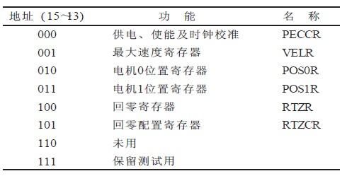
Table 1 MC33991 internal registers 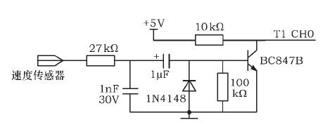
Figure 1 speed sensor signal conditioning circuit diagram 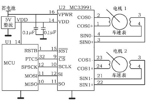
Figure 2 MC33991 and MCU interface circuit diagram
MC68HC908GR16 SPI clock pin SPSCK, host data input slave output pin MISO, host data output slave input pin MOSI and I / O pin PTC5, respectively connected to MC33991 SCLK, SO, SI, CS pin, RSTB The pin is connected to the RST pin of the microcontroller.
2.2 Software Design
2.2.1 SPI communication procedure
The MC33991 is initialized after the microcontroller MC68HC908GR16 is powered up. The SPI of the MC68HC908GR16 is set to master mode. The format of the transmitted data should conform to the timing of the MC33991 receiving and sending data. The timing of sending and receiving data of the MC33991 is shown in Figure 3. CS = 1 when there is no data transmission in the SPI, and the clock signal remains low. When there is data transfer, the SI pin of the MC33991 reads 1-bit data on the falling edge of the SCLK clock, and the output pin SO outputs data on the rising edge of the clock. Set the SPI register clock polarity bit COPL=0 of the MC68HC908GR16 and the clock phase control bit CPHA=1. Set the pin PTC5 direction register DDRC5=1 to set the output. Keep PTC5 high when communicating with MC33991. The data received by the MC33991 must be 16, 32, 48 bits each time. 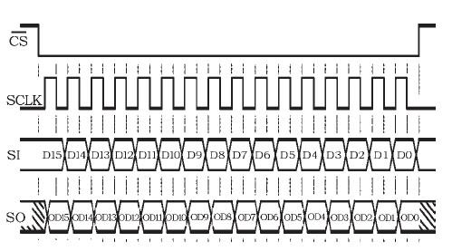
2.2.2 MC33991 Initialization Process
The initialization flowchart of MC33991 is shown in Figure 4. The microcontroller first sends a command to the PECCR to turn off the stepper motor and send a clock correction command if the two motors stop rotating. After clock correction, the internal clock of MC33991 is stable at 1 MHz (±10%). After the clock is corrected, the motor is enabled. Two or one of them can be allowed to work. Then send a command to register RTZCR to set the pointer to zero speed and send it to the VECR register. The command controls the maximum speed of the motor. If the pointer is not in a full step position when the stepper motor returns to zero or the magnetic field arrangement is not aligned, an error will occur in the MC33991 zero return detection, causing the zero return to fail. Therefore, before sending the motor zero return command, first advance the motor by 24 microsteps or 30, 36, 42 microsteps to keep the magnetic field aligned, then send the pointer back to zero command, and the pointer turns to the counterclockwise extreme of the motor. Only one pointer can be zeroed at a time, and the microcontroller detects the return to zero state until the end of zero return. 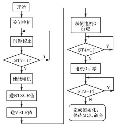
Note that the clock correction can be set to 1 MHz. After the MCU sends the clock correction command, the pin is pulled low and the delay is 8 μs before pulling it high. If the motor's gear reduction is low, select 0.667 MHz, which requires a delay of 12 μs.
2.2.3 Vehicle speed detection
After the MC33991 is initialized, the timer 1 channel zero of the MC68HC908GR16 is set to the input capture mode. The capture interrupt is entered on the falling edge of the input pulse, and the count difference Δt of the 2 falling edges is calculated. The maximum speed of the vehicle speed dashboard of this design is 120 km/h, the angle between the highest speed and the lowest speed is 225 °, and the static indicator of MC33991 is 2 700.
The driving speed of the car can be calculated by the following formula 
Where: n———the difference between the count values ​​of the counters in the 2nd speed pulse interval; T———the period of the microcontroller counter clock source; D———the outer diameter of the wheel; μ———the deformation coefficient of the automobile tire ( Generally take 0.93 ~ 0.96); N - - the number of pulses sent by the vehicle speed sensor after one round of the wheel.
Based on the calculated speed on the instrument panel, the microcontroller calculates the static indication position of the MC33991 and sends the static indication bit to the MC33991. The MC33991 drives the meter to the specified position. In order to speed up the running of the program, a constant Con is calculated according to the parameters of the vehicle speed and the speedometer of the vehicle speed. 
Where: vmax—the maximum speed indicated by the car dashboard; C———the constant used to adjust the pointer indication error. Where C is used to adjust the indicated position of the speedometer so that the indicating speed of the meter is not less than the actual speed of the car. Speedometer pointer should point
The position P0=Δt /Con, the microcontroller sends this position (P0) command directly to the MC33991. After the MC33991 receives the position command, it controls the instrument motor to rotate, pointing to the corresponding position of the dial.
3 Conclusion
This paper describes in detail the design of a car speedometer, designed using a dedicated integrated drive chip MC33991. When the watch is run on the test bench, the pointer can rotate smoothly, and there is no overshoot jitter when the acceleration is high. Compared with traditional mechanical instruments, this instrument has fast response, low jitter, high stability and reliability. Compared with stepper motor type instruments using other driver chips, this table first occupies less hardware resources, convenient control, and fast response of the instrument; secondly, it can return to zero at any set position at a constant speed, and there is no jitter when it reaches zero point; At the end of the instrument rotation, the microcontroller can read the working state of the stepper motor through the MC33991 at any time.
This article refers to the address: http://
Waterproof Power Supply,Waterproof Led Power Supply,Power Supply,Waterproof 12V Power Supply
Ninghai Yingjiao Electrical Co., Ltd. , https://www.yingjiaoadapter.com