
Design of Basic Control Circuit of Motor Based on PLC
In practical life applications, many mechanical equipments need to be able to run in both positive and negative directions, such as the positive and negative rotation of CNC machine tools, the rise and fall of elevators, and so on. In order to achieve this goal, this paper based on PLC technology, by changing the phase sequence of three-phase power supply, realizes the positive and negative control of the motor.
1 PLC technology
The Programmable Logic Controller (PLC) has become the most widely used and widely used industrial controller since its entry in 1969. It has several branches. PLC control consists of central processing unit CPU, memory power unit, etc., and has strong anti-interference ability. It is a class of programmable memory designed for industrial field applications. It is a combination of microcomputer technology and traditional relay contact control technology. It overcomes the complicated wiring, high power consumption and poor flexibility of the relay control system. The shortcomings, while taking care of the habits of maintenance personnel, can be flexibly applied in production practice.
The traditional relay control technology is realized by hardware wiring. If it is faulty, it is not convenient for maintenance. PLC control uses storage logic and stores it in the program in the program. If it is faulty, just check the program. The PLC's internal programmable structure mainly includes a programmer, an input and output unit, a user program memory, a system program memory, and a central processing unit.
From the point of view of control speed, the traditional relay control technology needs to be based on mechanical action due to the realization of control. Therefore, the working efficiency is low and the speed is slow. In the ns order and the operation is prone to jitter, the electrical appliance may be damaged. Because the PLC is controlled by the program, the speed is faster than the traditional relay control technology, the general speed is on the order of μs, and there is no jitter phenomenon during the control.
In the delay control, the traditional relay control technology relies on the hysteresis of the device, the timing accuracy is poor, and it is difficult to adjust the time during operation. The PLC monitor control is caused by the crystal oscillator, the control time is high, and the precision is high. Although PLC control is similar to microcomputer technology, it works differently. The PLC technology uses cyclic scanning, while the microcomputer uses keyboard scanning. Figure 1 is the working scanning mode of PLC technology.
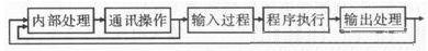
Figure 1 PLC scanning process
2Design of three-phase asynchronous forward and reverse control circuit of motor
In many operating systems, the motor is required to realize the forward and reverse operation. From the working principle of the motor, it is known that any two of the three-phase power supplies need to be reversed to realize the reverse operation of the motor, so the motor The essence of realizing the positive and negative reversal is the exchange of power supply lines. However, if only the incoming line is exchanged, it is easy to cause a short circuit of the power supply. Therefore, the interlock must be set. Figure 2 is the principle design diagram of the forward and reverse of the three-phase asynchronous motor. In the figure, both KM1 and KM2 are the main contacts of the AC contactor. When the KM1 is sucked At the same time, the main contact of the KM2 AC contactor will be disconnected, and then the forward rotation of the motor can be realized. If the main contact KM1 of the AC contactor is disconnected, the KM2 will be closed, and the motor will be reversed. The FU1 in the figure is mainly used to prevent the power supply from being short-circuited, and the circle represents the motor M.
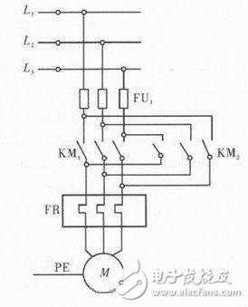
Figure 2 Principle design of the three-phase asynchronous motor forward and reverse
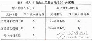
As can be seen from the above figure, the software interlock function of the PLC program is not reliable. Therefore, it is necessary to add interlocks in the hardware. The address allocation table is shown in Table 1. In addition to adding interlocks in the hardware, a thermal protection device is required.
Table 1 Input (1) Address and Output Address (0) Allocation Table
According to the specific functions and requirements of the designed device, the PLC ladder diagram is drawn. The ladder diagram is shown in Figure 3. Then parse it to get the programming code.
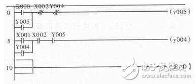
Figure 3 ladder diagram
The designed procedure is as follows:
0 LD X000
1 OR Y005
2 ANI X002
3 ANI Y004
4 OUT Y005
5 LD X001
6 OR Y004
7 ANI X002
8 ANI Y005
9 OUT Y004
10 END
In the ladder diagram of Figure 3, the normally open contacts controlled by the external buttons of the PLC are mainly the first level of the left busbar and the X001 contacts and X002 contacts of the second level. The button can make X000 or X001 any one of the usual. When the open contact is closed, the output relay Y005 or the relay Y004 can form a closed loop through the corresponding line, thereby enabling the normally open contact point Y005 or Y004 to realize the self-locking function and simultaneously realize the forward and reverse rotation of the motor. Stopping is achieved by a button external to the PLC. By releasing the X002 normally open contact point, the relay is de-energized and the motor is stopped.
3 Conclusion
The paper designs the three-phase asynchronous forward and reverse control circuit of the motor. The experiment proves that the design can achieve the positive and negative control of the click, but there are still some areas for improvement in the control, such as the low degree of automation, in practice. There are still many inconveniences in the operation.
LED Fountain Light adopts stainless steel integrated Lamp body, tempered glass and product patented technology, and a new type of underwater fountain lamp produced by a fully waterproof production process. LED Fountain Lights are widely used in square fountains, Swimming Pool fountains, beach fountains and so on. Most of them are used in large-scale musical fountain squares. One is for aesthetics and the other is for convenience. Most of the fountain spray fountain installations are embedded in the ground, and the lamp surface is generally flush with the ground to facilitate pedestrian movement. In addition, the fountain light has a soft light color, which not only provides comfortable visual conditions for people, but also reflects the lighting style of the landscape through the coordination of various light colors to increase the artistic beauty.
LED Fountain Light
LED Pool Table Light Kit,LED Pool Light Cost,LED Fountain Light,LED Fountain Lights Submersible
JIANGMEN LEDERLIGHT LIGHTING Co.,LTD , https://www.lederlight.com