
LED de-powered analysis of the general technical route to reduce stroboscopic
The industry is currently discussing "de-energization", which includes some functional modules that do not use power or remove power. De-energization can also be performed at different levels, including at the chip level, at the electronic component level, at the luminaire level.
The current situation: de-energization at different levels, using a variety of patented technical routes with completely different principles.
Question: Is there a general-purpose stroboscopic reduction principle and a patented technical route based on this principle that can be applied to all levels without the need to develop different technical approaches using different principles for different levels?
This article describes a general principle of reducing strobe and a technical route based on this principle.
The technical route is characterized by the principle that it can be applied to both chip level, electronic component level, and lamp/circuit level.
The following is a brief introduction to the general principle of reducing strobe.
To simplify drawing and analysis, assume:
(1) The waveform of the alternating current after phase shifting remains unchanged, and is still a sine wave. Although the waveform changes after phase shifting, it does not affect the general principle of reducing stroboscopic, and only needs to adjust the phase difference between different input AC currents in order to achieve the desired result;
(2) In the operating current range, the luminance of the light is substantially proportional to the current (Lumileds). Therefore, although only the current is analyzed below, the conclusion applies to the luminance of the light.
It is well known that the effect of stroboscopic light on the human eye depends mainly on the difference between the maximum and minimum brightness (percent stroboscopic) and the oscillation frequency of the maximum.
The basic principle of general use is: input AC currents of different phases, respectively rectify and superimpose to form the total current, and drive the LED lamps with the total current. The result is:
(1) the oscillation frequency of the maximum value of the total current increases, and therefore, the oscillation frequency of the maximum value of the light luminance increases;
(2) the difference between the maximum value and the minimum value of the total current is reduced, and therefore, the percentage strobe of the lightness is reduced;
(3) The total voltage after superposition is not equal to 0 (or less than 2.8 volts). Therefore, the luminaire has no moment of non-lighting.
Therefore, the strobe of the brightness of the total current driven LED luminaire is reduced to the same or even better level than other luminaires, ie, this principle can achieve the stroboscopic requirements for the luminaire.
Here are a few examples to illustrate how the general principle of reducing strobe reduces strobe.
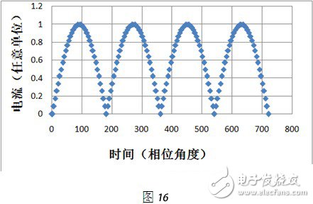
An input sinusoidal AC current: The normalized waveform after rectification is as follows (Figure 16):
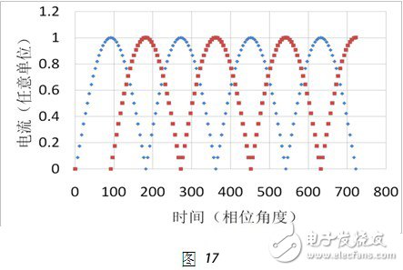
For two input sinusoidal AC currents with a phase difference of 90°: rectified separately, but not superimposed on each other, the normalized pattern of two pulsating DC currents is shown in Figure 17:
The pulsating DC currents obtained by rectifying the input sinusoidal alternating currents of two input phases with a phase difference of 90° shown in FIG. 17 are superimposed to obtain a total current. The normalized total current waveform is shown in Fig. 18 (the maximum value of the total current after rectification by the sinusoidal alternating current of two input without phase difference is 1).
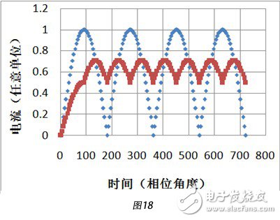
In order to demonstrate the general function of reducing the principle of stroboscopic, a comparison is made: in Fig. 18, the diamond represents the normalized total current of the sinusoidal alternating currents of the two input without phase difference, and the superposition, and the square represents two phases. The input sinusoidal alternating currents with a phase difference of 90° are respectively rectified and superimposed normalized total currents (rectified by two sinusoidal alternating currents with no phase difference input, and the maximum value of the superimposed total current is 1).
Portable Battery Pack,Wireless Battery Pack,Rechargeable Battery Pack,Nintendo Switch Battery Pack
Zhejiang Xinghai Energy Technology Co.,Ltd , https://www.headwayli-battery.com