
Research on Liquid Crystal Display Technology of Low-Cost Single-Chip System
1 Introduction
With the rapid development of electronic technology, the design of electronic circuits is becoming more and more complicated. Because of its high integration, high stability and low cost, single-chip microcomputers are more and more widely used in electronic design.
First, the use of digital display tubes is low cost, but the display content is very limited and single, and can not meet more and more display requirements. Second, the use of CRT or color liquid crystal display can display more content, but there are complex designs. Draw down, improve design costs and waste resources. Therefore, in practice, there is an urgent need for a simple and practical, low-cost, simple design display of its products.
2. Basic principles
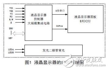
The LC0811-SL consists of a liquid crystal display controller and a liquid crystal display panel and an LED backlight. The liquid crystal display controller is the core part of the entire display. Its internal structure is shown in Figure 1.
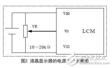
2.1 Power supply
The liquid crystal display uses a 5V DC power supply, and the power supply schematic is shown in Figure 2.
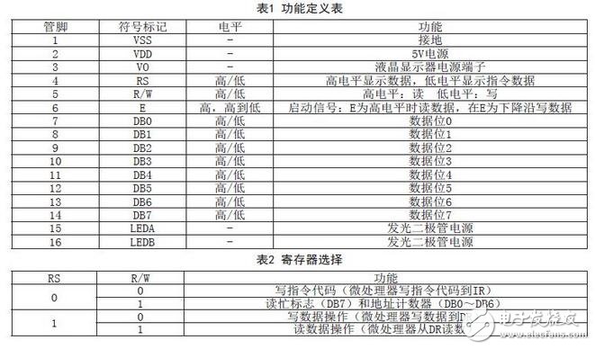
2.2 Pin Function Definition
The LC0811-SL has 16 pins (PIN), and the specific functions are defined as shown in Table 1 and Table 2.
2.3 register
The LCD controller has two 8-bit registers, an instruction register (IR) and a data register (DR).
The Instruction Register (IR) is a write-only register that is used to store instruction code such as clear display or cursor shift, and to store display data RAM (DD RAM) address or character generator RAM (CG RAM) address.
The data register (DR) is a read/write register for temporarily storing data read/write to DD RAM or CG RAM. The data write DR is automatically written to the DD RAM or CG RAM through an internal operation of the display controller. At the same time, DR is also used to store data read from DD RAM or CG RAM. When the address information is written to the IR, the data is read from the DD RAM or the CG RAM to the DR through an internal operation, and the data transfer at this time is completely completed by reading the DR. After performing a read operation from DR, the data is saved in DD RAM or CG RAM, and the next address is sent to DR to prepare for the next read cycle. As shown in Table 2, the Register Selector (RS) signal determines two. Which one of the registers is selected.
2.4 Busy Sign (BF)
An internal operation is performed when the busy flag is 1 (ie, high) and the next instruction is unacceptable.
When RS=0 and a read operation is performed, the busy flag is output to DB7, and the next instruction can be written only when the busy flag is 0 (ie, low).
2.5 Address Counter (AC)
The address counter allocates an address to DDRAM or C GRAM. When an instruction's address is written to IR and the address information is sent from IR to AC, this instruction also determines the DD RAM or CGRAM selection. After a read/write operation is completed from DD RAM or CG RAM, the address counter (AC) is automatically decremented by 1 or incremented by 1. When RS=0 and the read operation is completed, the contents of the AC are output to DB0DB0~DB7.
2.6 Display Data Memory (DD RAM)
The DD RAM stores the display data in the form of an 8-bit character code with a capacity of 80*8 or 80 bytes. When the DD RAM is not used for display, it can be used as general-purpose data RA M.
The DD RAM address is set by AC and is represented in hexadecimal. This address counter can be written by the "Set DD RAMAddress" instruction and read by the "Read BusFlag and Address" instruction. As shown in FIG. 3, during read/write, data bits DB0~DB6 represent DDRAM addresses, and DB7 is a busy flag bit.
2.7 character generator ROM (CG ROM)
The character generator ROM (CG ROM) generates 5&TImes; 7 dot matrix or 5&TImes; 10 dot matrix character graphics from 8-bit character codes, which can produce equal to 192 kinds of 5&TImes; 7 dot matrix character graphics and 32 kinds of 5&TImes; 10 dot matrix character graphics .
Glass Bowl Food Choppers are our main food choppers. We have 0.6L, 1.2L, 1.8L optional with pure clear and thick glass bowl. Besides, we have molding polyfoam packing for glass bowl and our glass bowl is thick and strong, it is not easy broken. What's more, glass bowl is easy to clean.
Description of Glass Bowl Food Choppers
300W/350W
S/S housing
pure clear and thick glass bowl with double blades
one/two speeds with safety lock
metal gear
6pcs/ctn

Glass Bowl Food Choppers
Glass Bowl Food Choppers,Glass Bowl Choppers,Kitchen Food Processor,Vegetable Chopper
Flying Electronic Co., Ltd , https://www.flyingelectronic.com